Prosthetic mitral valve

a prosthetic and valve body technology, applied in the field of prosthetic mitral valves, can solve the problems of increasing the workload placed on the heart, exhibiting relatively poor hemodynamic properties, and the thrombogenicity of available artificial tissue valves

Inactive Publication Date: 2007-07-26
MEDTRONIC 3F THERAPEUTICS
View PDF99 Cites 227 Cited by
  • Summary
  • Abstract
  • Description
  • Claims
  • Application Information

AI Technical Summary

Benefits of technology

[0018] For purposes of summarizing the invention and the advantages achieved over the prior art, certain aspects and advantages of the invention have been described herein above. Of course, it is to be understood that not necessarily all such aspects or advantages may be achieved in accordance with any particular embodiment of the invention. Thus, for example, those skilled in the art will recognize that the invention may be embodied or carried out in a manner that employs one or more aspects to achieve or optimize one advantage or group of advantages as taught herein without necessarily using other aspects or achieving other advantages as may be taught or suggested herein.

Problems solved by technology

Both of these abnormalities increase the workload placed on the heart.
Some of the available mechanical valves are durable, but tend to be thrombogenic and exhibit relatively poor hemodynamic properties.
Some of the available artificial tissue valves may have relatively low thrombogenicity, but lack durability.
Additionally, even artificial tissue valves often do not exhibit hemodynamic properties that approach the advantageous hemodynamic performance of a native valve.

Method used


Image

  • Prosthetic mitral valve
  • Prosthetic mitral valve
  • Prosthetic mitral valve

Examples


Embodiment Construction

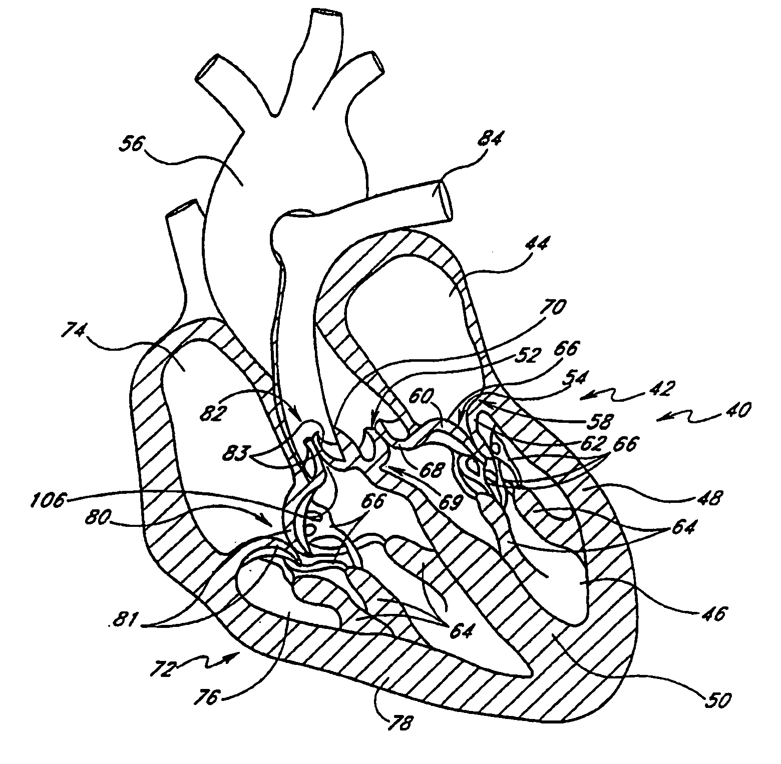
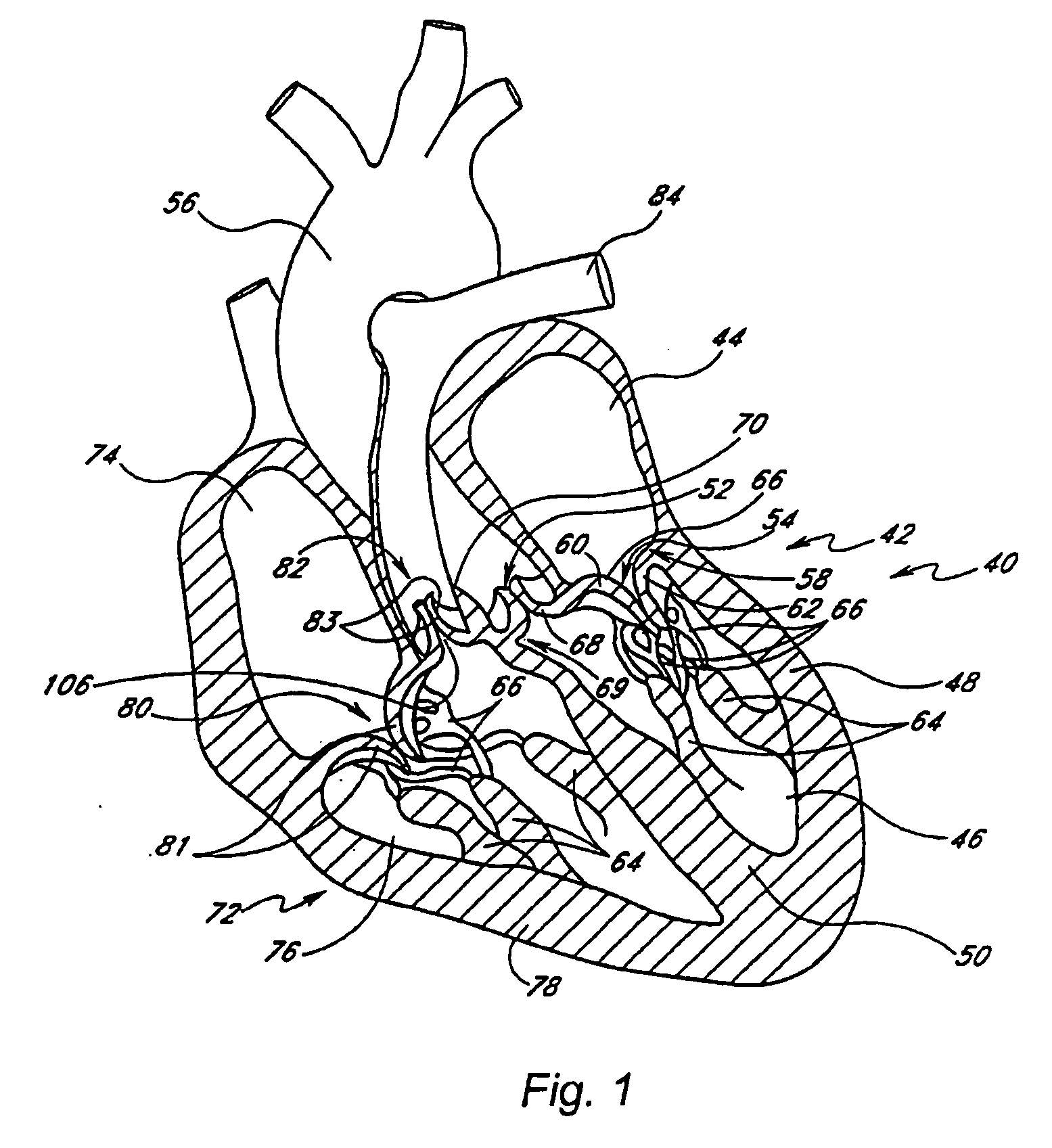
[0070]FIG. 1 is a cross-sectional cutaway depiction of a typical human heart 40. The left side 42 of the heart 40 includes a left atrium 44 and a left ventricular chamber 46. The left ventricle 46 is defined between a left ventricular wall 48, a septum 50, an aortic valve assembly 52 and a mitral valve assembly 54. The mitral valve assembly 54 is positioned generally between the left ventricle 46 and the left atrium 44 and regulates blood flow from the atrium 44 into the ventricle 46. The aortic valve assembly 52 is positioned atop the left ventricle 46 and regulates blood flow from the left ventricle 46 into an aorta 56.

[0071] The mitral valve assembly 54 includes a mitral valve annulus 58; an anterior leaflet 60 (sometimes called the aortic leaflet, since it is adjacent to the aorta); a posterior leaflet 62; two papillary muscles 64, which are attached at their bases to the interior surface of the left ventricular wall 48; and multiple chordae tendineae 66, which extend between t...


PUM


Abstract

An improved prosthetic mitral valve is provided having advantageous hemodynamic performance, nonthrombogenicity, and durability. The valve includes a valve body having an inflow annulus and an outflow annulus. Commissural attachment locations are disposed adjacent the outflow annulus. An anterior leaflet and a posterior leaflet of the valve are shaped differently from one another. The inflow annulus preferably is scalloped so as to have a saddle-shaped periphery having a pair of relatively high portions separated by a pair of relatively low portions. The anterior high portion preferably is vertically higher than the posterior high portion.

Description

CROSS REFERENCE TO RELATED APPLICATIONS [0001] This application is a continuation of U.S. patent application Ser. No. 10 / 668,650 filed Sep. 23, 2003, which claims priority under 35 U.S.C. 119(e) to U.S. Provisional Patent Application No. 60 / 413,266, filed Sep. 23, 2002, the entireties of which are herein incorporated by reference.FIELD OF THE INVENTION [0002] The present invention relates to an improved prosthetic mitral valve and an apparatus for testing prosthetic mitral valves. BACKGROUND OF THE INVENTION [0003] A natural human heart has four valves that serve to direct blood now through the heart. On the right (pulmonary) side of the heart are: (1) the tricuspid valve, which is positioned generally between the right atrium and the right ventricle, and (2) the pulmonary valve, which is positioned generally between the right ventricle and the pulmonary artery. These two valves direct de-oxygenated blood from the body through the right side of the heart and into the pulmonary arter...

Claims


Application Information

Patent Timeline
Patent Type & Authority Applications(United States)
IPC IPC(8): A61F2/24A61BA61B1/00
CPCA61F2/2412A61F2220/0075A61F2/2457
Inventor CALI, DOUGLAS S.MYERS, KEITH E.BIANCUCCI, BRIANARTOF, JASONNGUYEN, CHRISTINE T.QUIJANO, RODOLFO C.
Owner MEDTRONIC 3F THERAPEUTICS
Why Eureka
Try Eureka