Method of treating a gaseous mixture comprising hydrogen and carbon dioxide

a gaseous mixture and carbon dioxide technology, applied in the direction of hydrogen separation using liquid contact, separation process, energy input, etc., can solve the problems of reducing the quantity of low grade heat available, requiring significant utility consumption, and deficits to be made up

Active Publication Date: 2007-08-02
AIR PROD & CHEM INC
View PDF8 Cites 108 Cited by
  • Summary
  • Abstract
  • Description
  • Claims
  • Application Information

AI Technical Summary

Benefits of technology

[0060] One particular advantage of the present invention is that at least a portion (and usually all) of the possible harmful trace components will be oxidized and converted to soluble or inactive forms which can be removed downstream, often more easily than the harmful trace components themselves.
[0061] The CO2 product gas may comprise a number of contaminants. The identity and amount of the contaminants depends on the nature of the fuel used to produce the gaseous mixture, the conditions of the combustion step and the effectiveness of the separation. For example, the use of coal as a fuel produces H2S which, when combusted, produces SO2 and SO3 (or “SOx”). Excess O2 in the combustion step could result in O2 as a contaminant. In addition, N2 and Ar, originating as impurities in the O2 used in the combustion, could also be present as contaminants in the CO2 product gas. However, one advantage of the use of an oxyfuel combustion process is that N2 and Ar are largely eliminated from process except for the quantities present with the O2 feed and also as a result of air leaking into the process. The N2 and Ar components are termed “inert” components.
[0065] separating the sulfuric acid and / or nitric acid from the cooled, SO3-free, CO2 product gas to produce SOx-free, NOx-lean CO2 gas.
[0066] The term “free” in the context of “SO3-free” or “SOx-free” means that at least substantially all (and usually essentially all or preferably all) SO3 or SOx has been removed.
[0067] At least a portion of the SOx-free, NOx-lean CO2 gas may then be dried, purified to remove “inert” components if necessary, and compressed to a pipeline pressure of from about 80 bar to about 250 bar.
[0068] Typically, at least substantially all (and usually all) of any SOx contaminant and the bulk, usually about 90%, of any NOx is removed.

Problems solved by technology

Current technology would then be used to selectively separate H2S and CO2 from H2, usually by passing the gas into a physical solvent absorption process which are expensive and require significant utility consumption during operation.
Both these effects reduce the quantity of low grade heat available for condensate heating prior to de-aeration and boiler feed water heating following condensate pumping to steam delivery pressure.
This still leaves a deficit which must be made up by using intermediate pressure steam bled from the steam power cycle or some other means.

Method used


Image

  • Method of treating a gaseous mixture comprising hydrogen and carbon dioxide
  • Method of treating a gaseous mixture comprising hydrogen and carbon dioxide
  • Method of treating a gaseous mixture comprising hydrogen and carbon dioxide

Examples


example 1

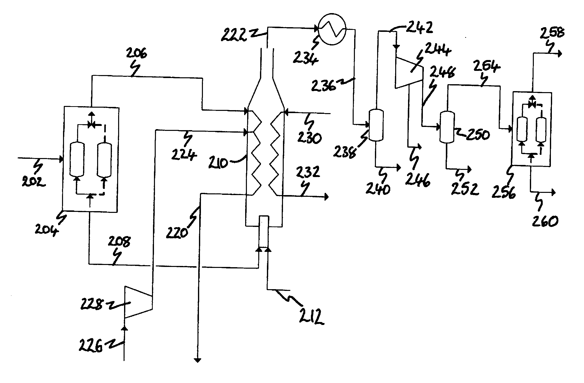
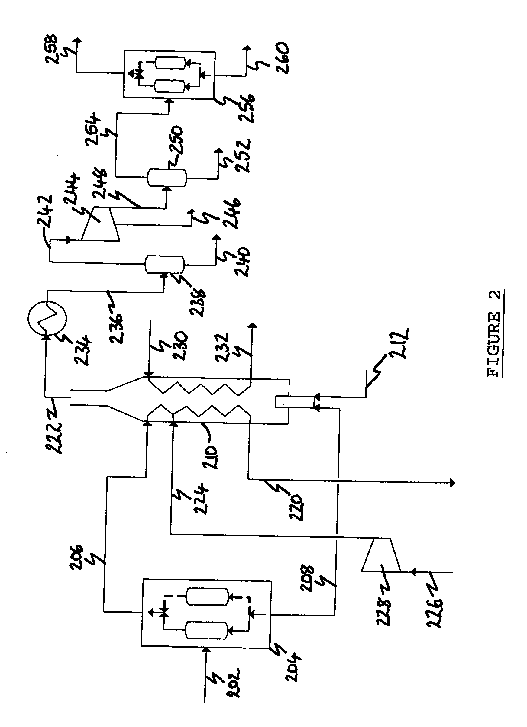
[0201] In Example 1, the computer simulated the arrangement of the process depicted in FIG. 2 in which synthesis gas is produced from natural gas in an ATR (not shown). The synthesis gas is cooled to 40° C. and condensed water removed prior to being fed as stream 202 to the H2 PSA 204 which is operating to produce pure (100 mol. %) H2 at 90 mol. % recovery.

[0202] The results of the simulation in Example 1 are provided in Table I.

TABLE IStream Number202206208226224220212230232222Temperature° C.40.0040.0040.0015.0096.00350.00200.0035.00500.0069.44Pressurebar a27.527.527.5323231.51501501.5Flowkg / s61.256.4254.8393.1693.1699.588.1419.7819.7862.98CompositionH2mol %73.4671100.000021.68480.00000.000049.06760.00000.00000.00000.0000COmol %1.53980.00004.54500.00000.00000.00000.00000.00000.00000.0000CO2mol %24.06610.000071.03410.00000.00000.00000.00000.00000.000074.4275H2Omol %0.30650.00000.90470.00000.00000.00000.0000100.0000100.000023.3702CH4mol %0.22950.00000.67750.00000.00000.00000.00000...

example 2

[0203] The process arrangement simulated in Example 2 is identical to that simulated in Example 1 except that the H2 PSA 204 is optimized for this application. The H2 recovery is increased (to 92 mol. %) and its purity is decreased by designing the PSA to allow some impurities through with the H2. This allows a smaller PSA to be used, and also has the surprising benefit that, in allowing inerts to come through with the hydrogen, higher purity CO2 is produced.

[0204] The results of the simulation in Example 2 are provided in Table II.

TABLE IIStream Number202206208226224220212230232222Temperature° C.40.0040.0040.0015.0096.00350.00200.0035.00500.0067.01Pressurebar a27.527.527.5323231.51501501.5Flowkg / s61.257.3753.8995.5895.58102.956.6711.8311.8360.56CompositionH2mol %73.467199.148618.46500.00000.000048.77120.00000.00000.00000.0000COmol %1.53980.56473.62820.00000.00000.27780.00000.00000.00000.0000CO2mol %24.06610.000075.60850.00000.00000.00000.00000.00000.000077.9807H2Omol %0.30650.00...

example 3

[0205] In Example 3, the computer simulated an alternative arrangement of the process depicted in FIG. 2. In this alternative arrangement, synthesis gas is produced from the gasification of coal in a gasifier (not shown). As in Examples 1 and 2, the synthesis gas is cooled to 40° C. and condensed water removed prior to being fed as stream 202 to the H2 PSA 204. The PSA is operating to produce pure (100 mol. %) H2 at 90 mol. % recovery.

[0206] The synthesis gas will contain H2S which will combust to produce SO2 which can be removed as sulfuric acid in the compression system by the addition of NOx.

[0207] The results of the simulation of Example 3 are provided in Table III.

TABLE IIIStream Number202206208226224220212230232222Temperature° C.40.0040.0040.0015.0096.00350.00200.0035.00500.0058.12Pressurebar a27.527.527.5323231.51501501.5Flowkg / s120.316.05114.2687.6487.6493.689.3823.2123.21123.64CompositionH2mol %55.5876100.000011.12390.00000.000049.08380.00000.00000.00000.0000COmol %1.85...


PUM

PropertyMeasurementUnit
pressureaaaaaaaaaa
pipeline pressureaaaaaaaaaa
temperatureaaaaaaaaaa

Abstract

Hydrogen (H2) gas and crude carbon dioxide (CO2) gas are separated from a gaseous mixture thereof. Combustible gas(es) in the crude CO2 gas are combusted to produce heat, at least a portion of which is recovered by indirect heat exchange with at least a portion of the separated H2 gas or a gas derived therefrom. The invention may be integrated with coal-fired power stations to reduce or eliminate emission of harmful components into the atmosphere.

Description

BACKGROUND OF THE INVENTION [0001] The present invention relates to a method of treating a gaseous mixture comprising hydrogen (H2), carbon dioxide (CO2) and at least one combustible gas selected from the group consisting of hydrogen sulfide (H2S), carbon monoxide (CO) and methane (CH4). The invention is preferably integrated with fossil fuel-fired power stations to reduce or eliminate emission of CO2 and other atmospheric pollutants. The main fuel of interest is coal although the invention has application in the generation of power from other fuels such as bitumen, petcoke and natural gas. [0002] There is an need to develop improved methods for efficient power generation from fossil fuels, including carbonaceous and hydrocarbonaceous fuels, and biomass fuel, with virtually zero emission of atmospheric pollutants, particularly CO2. There are three basic techniques in the context of CO2 capture from power generation equipment using these types of fuel: [0003] (a) pre-combustion decar...

Claims


Application Information

Patent Timeline
Patent Type & Authority Applications(United States)
IPC IPC(8): B01D53/22C01B32/50
CPCC01B3/52C01B3/56C01B31/20C01B2203/0415Y02E20/16C01B2203/0475Y02C20/20Y02E20/18C01B2203/043Y02P20/129C01B32/50Y02P20/133
Inventor WHITE, VINCENTALLAM, RODNEY JOHN
Owner AIR PROD & CHEM INC
Why Eureka
Try Eureka