Exhaust gas turbocharger for a reciprocating internal combustion engine and corresponding reciprocating internal combustion engine

a technology of exhaust gas and internal combustion engine, which is applied in the direction of machines/engines, stators, liquid fuel engines, etc., can solve the problems of unfavorable fuel consumption, and achieve the effects of improving efficiency, improving turbine efficiency, and improving turbine efficiency

Active Publication Date: 2007-08-09
DAIMLER TRUCK AG
View PDF4 Cites 28 Cited by
  • Summary
  • Abstract
  • Description
  • Claims
  • Application Information

AI Technical Summary

Benefits of technology

[0005] In an exhaust gas turbocharger for a reciprocating internal combustion engine comprising an exhaust gas turbine in the exhaust line and a compressor in the inlet line of the engine, the exhaust gas turbine has two exhaust gas flow passages, by way of which exhaust gas be fed to the turbine rotor. In accordance with the invention, the efficiency of the turbine is improved in that the ratio of the turbine rotor diameter to the compressor wheel is selected so as to exceed a linear function, which depends substantially on the total displacement volume of the internal combustion engine and the degree of asymmetry specific to the turbine, the degree of asymmetry representing the ratio of the choke flow rate parameters for the two exhaust gas flow passages. This relationship serves to ensure that the turbine rotor diameter has a defined minimum size compared to the compressor wheel diameter, which affords the advantage that the circumferential speed increases on the outer diameter of the turbine rotor thereby also improving the turbine efficiency. This improvement in efficiency compensates for an inherent impairment of efficiency brought about by the asymmetrical design of the two exhaust gas flow passages of the exhaust gas turbine. Such an asymmetrical configuration of the exhaust gas flow passages, however, is desirable for effective exhaust gas recirculation, which improves the exhaust emission properties and has a favorable influence on fuel consumption. The advantage of exhaust gas recirculation can therefore be combined with the advantage of improved turbine efficiency. These two measures in conjunction lead to improved exhaust emissions and lower fuel consumption.

Problems solved by technology

In addition, exhaust gas recirculation with asymmetrical turbine inlet flow passages leads to favorable fuel consumption.

Method used


Image

  • Exhaust gas turbocharger for a reciprocating internal combustion engine and corresponding reciprocating internal combustion engine
  • Exhaust gas turbocharger for a reciprocating internal combustion engine and corresponding reciprocating internal combustion engine
  • Exhaust gas turbocharger for a reciprocating internal combustion engine and corresponding reciprocating internal combustion engine

Examples


Embodiment Construction

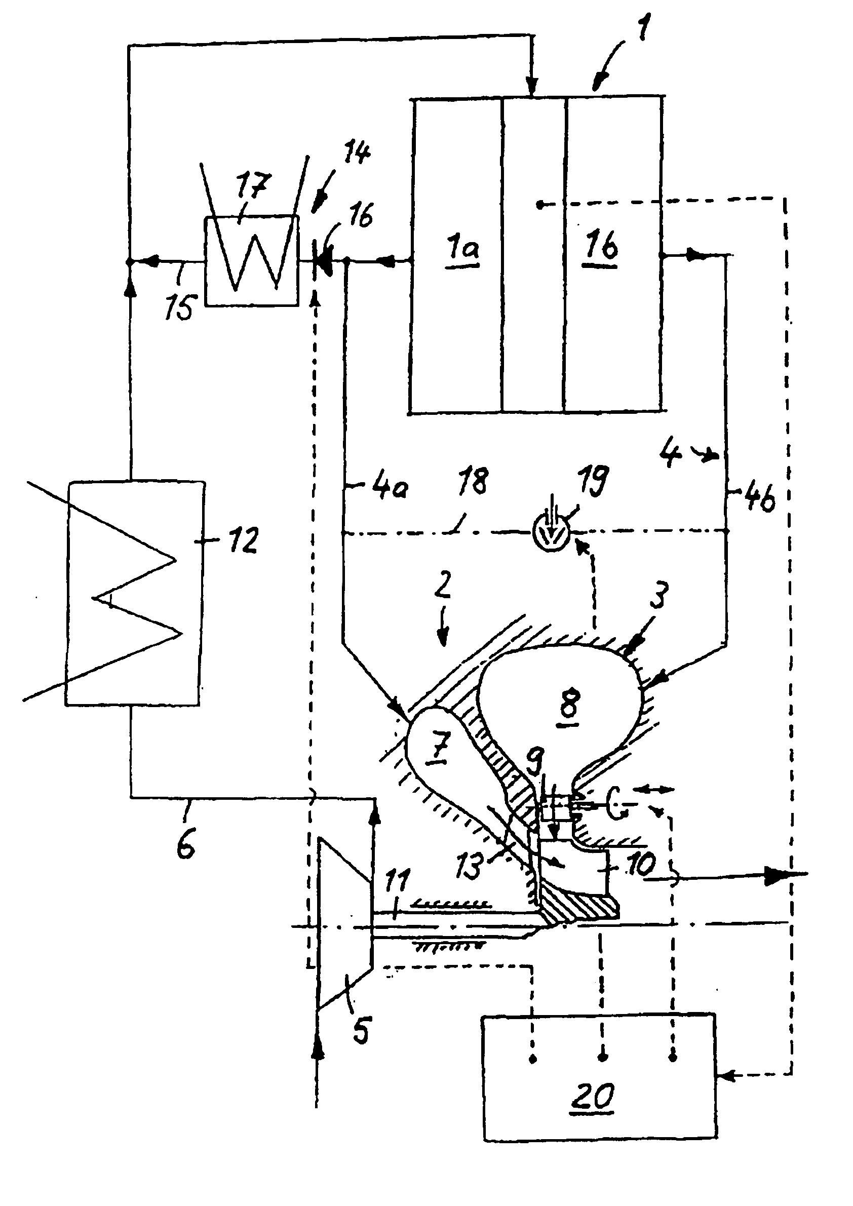
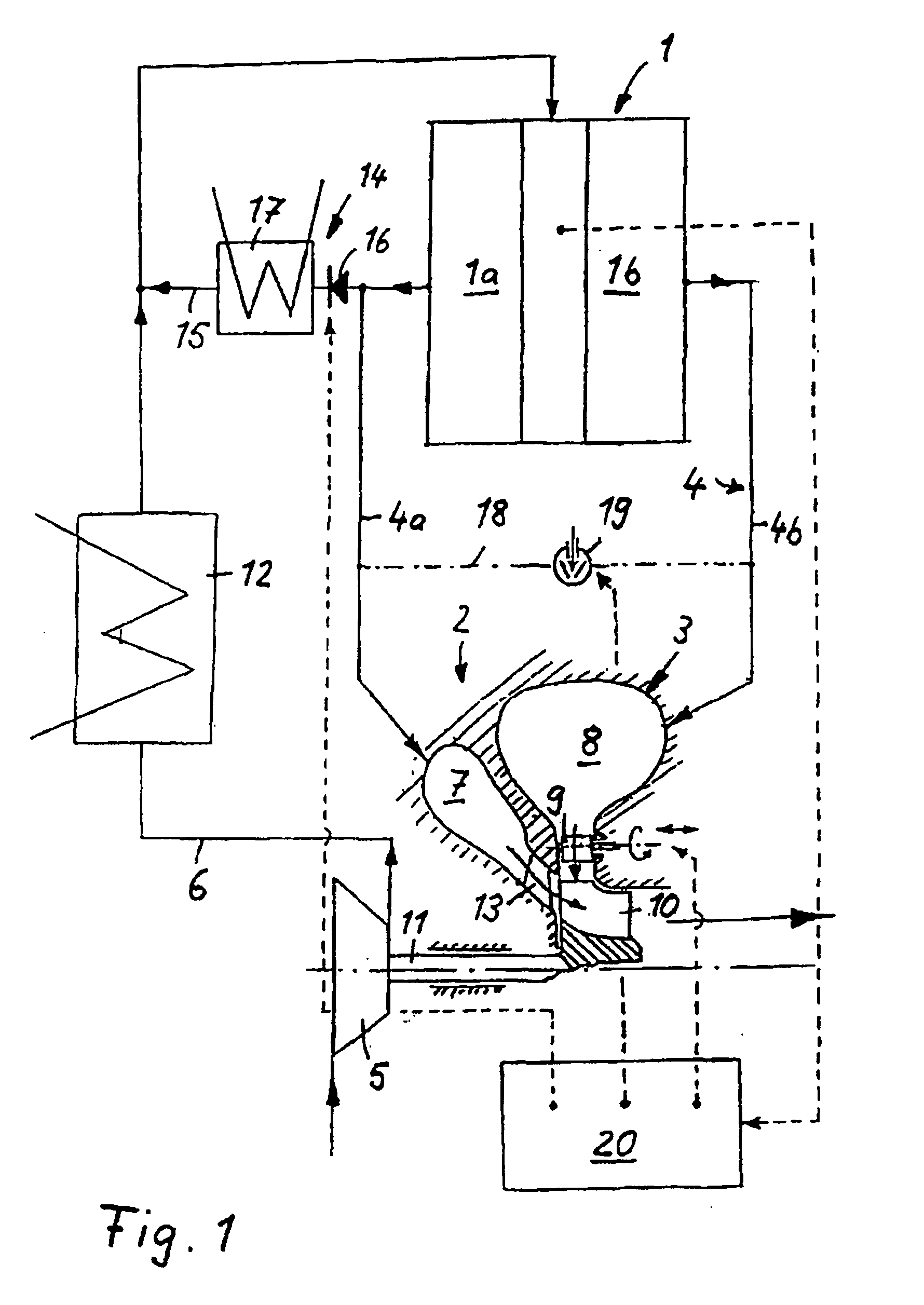
[0016] The internal combustion engine 1 represented in FIG. 1 is a spark-ignition engine or a diesel engine having two separate cylinder banks 1a and 1b. An exhaust gas turbocharger 2 having an exhaust gas turbine 3 in the exhaust manifold 4 and a compressor 5 in the inlet manifold 6 is assigned to the internal combustion engine 1. The turbine rotor 10 of the exhaust gas turbine 3 is driven by the pressurized exhaust gases from the internal combustion engine, the rotation of the turbine rotor 10 being transmitted by way of a shaft 11 to the compressor wheel in the compressor 5, whereupon ambient air is drawn into the inlet manifold 6 and is compressed to a higher boost pressure. The compressed air is then cooled in an air intercooler 12 downstream of the compressor 5 before subsequently being delivered at boost pressure to the cylinders of the internal combustion engine 1.

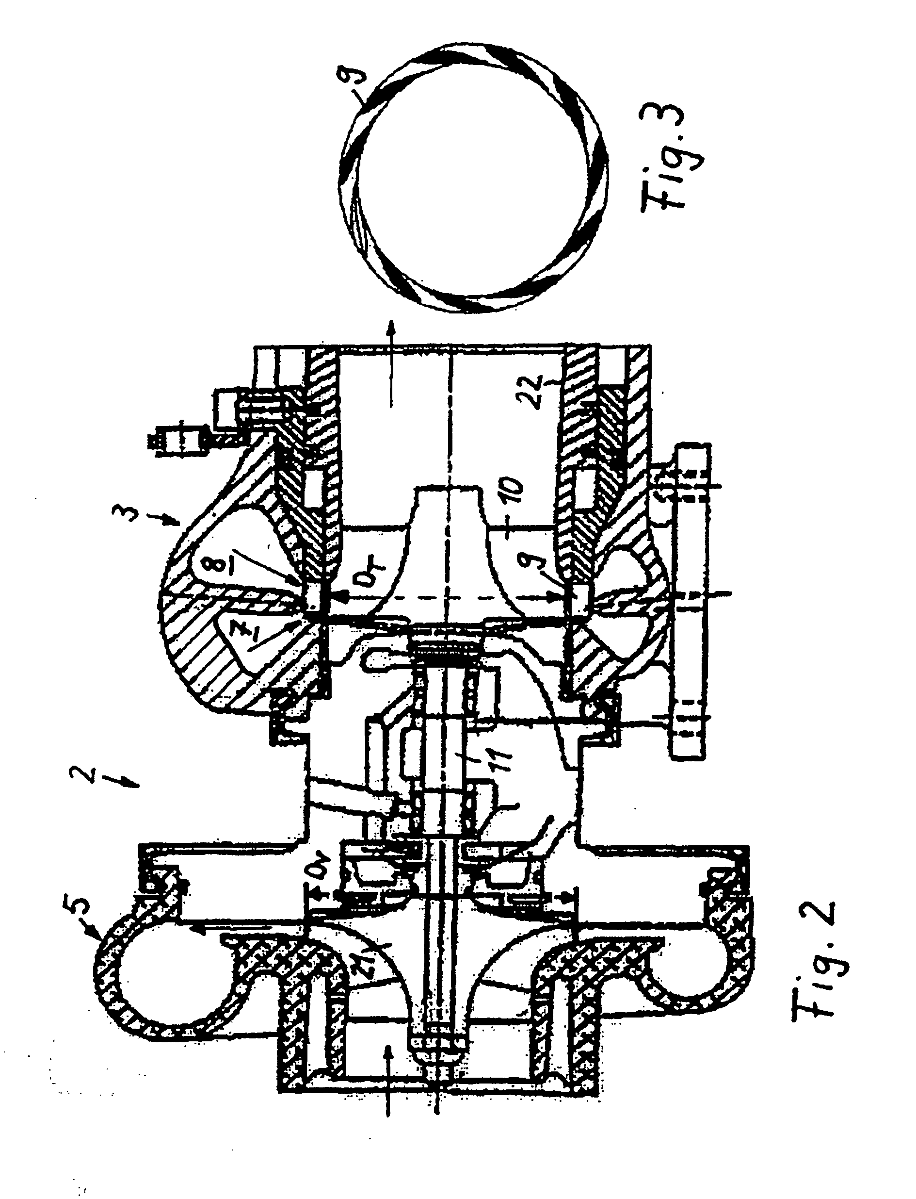
[0017] The exhaust gas turbine is of double-flow construction and has a first, smaller exhaust gas flow passage...


PUM


Abstract

In an exhaust gas turbocharger for a reciprocating internal combustion engine comprising an exhaust gas turbine in the exhaust line and a compressor in the inlet line of the engine, the exhaust gas turbine has two exhaust gas flow passages, by way of which exhaust gas is fed to the turbine rotor, the ratio of the turbine rotor diameter to the compressor wheel diameter being set by a function, which is dependent on the displacement volume of the internal combustion engine.

Description

[0001] This is a Continuation-In-Part Application of pending International Patent Application PCT / EP2005 / 006610 filed Jun. 18, 2005 and claiming the priority of German Patent Application 10 2004 030 703.2 filed Jun. 25, 2004. BACKGROUND OF THE INVENTION [0002] The invention relates to an exhaust gas turbocharger for a reciprocating internal combustion engine and to a c reciprocating internal combustion engine including an exhaust gas turbocharger to which exhaust gas is supplied from the internal combustion engine via two separate exhaust ducts. [0003] DE 101 52 804 A1 describes an exhaust gas turbocharger for an internal combustion engine, which comprises an exhaust gas turbine in the exhaust manifold and a compressor in the inlet manifold, the turbine rotor being driven by the pressurized exhaust gases from the internal combustion engine and the rotation of the turbine rotor being transmitted by a shaft to the compressor wheel, which thereupon draws in ambient air and compresses i...

Claims


Application Information

Patent Timeline
Patent Type & Authority Applications(United States)
IPC IPC(8): F02B29/04F02B33/44F01D5/14F02B37/02F02B37/22F02M25/07
CPCF02B37/02Y02T10/144F02B37/22F02B37/025Y02T10/12
Inventor SUMSER, SIEGFRIEDSCHMID, WOLFRAMFINGER, HELMUT
Owner DAIMLER TRUCK AG
Why Eureka
Try Eureka