

Mass spectrometer
a mass spectrometer and mass spectrometer technology, applied in the direction of isotope separation, electric discharge tubes, separation processes, etc., can solve the problems of inability to perform mssup>n /sup>analysis and inability to detect ions
- Summary
- Abstract
- Description
- Claims
- Application Information
AI Technical Summary
Benefits of technology
Problems solved by technology
Method used
Image

Examples
first embodiment
[0042]In the first embodiment, the system is described in which a sample ion for dissociation is resonance excited and oscillated in the axial direction by the Supplemental AC voltage, and is dissociated due to collision with neutral gas molecules in the linear ion trap having multipole electrodes.
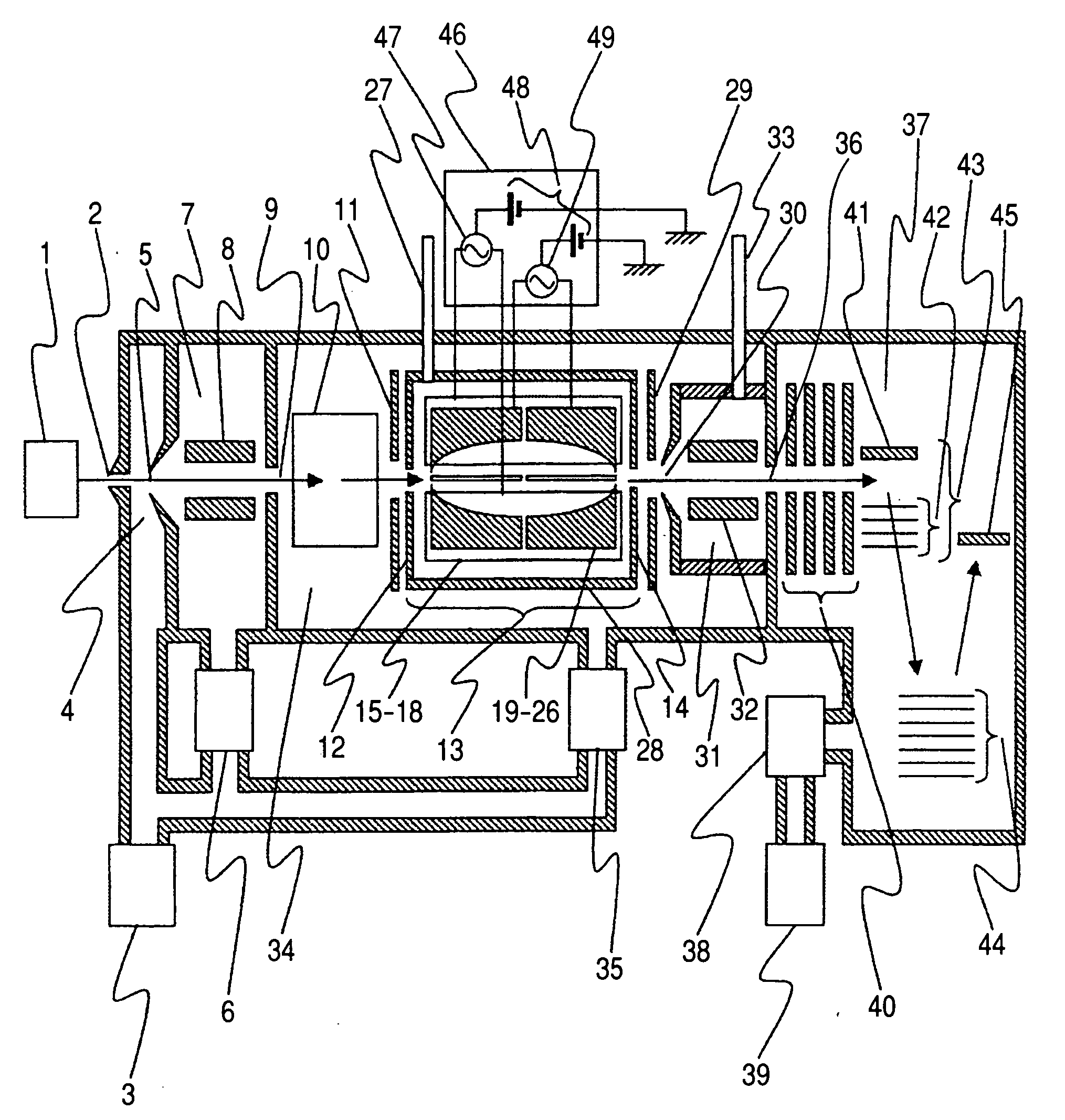
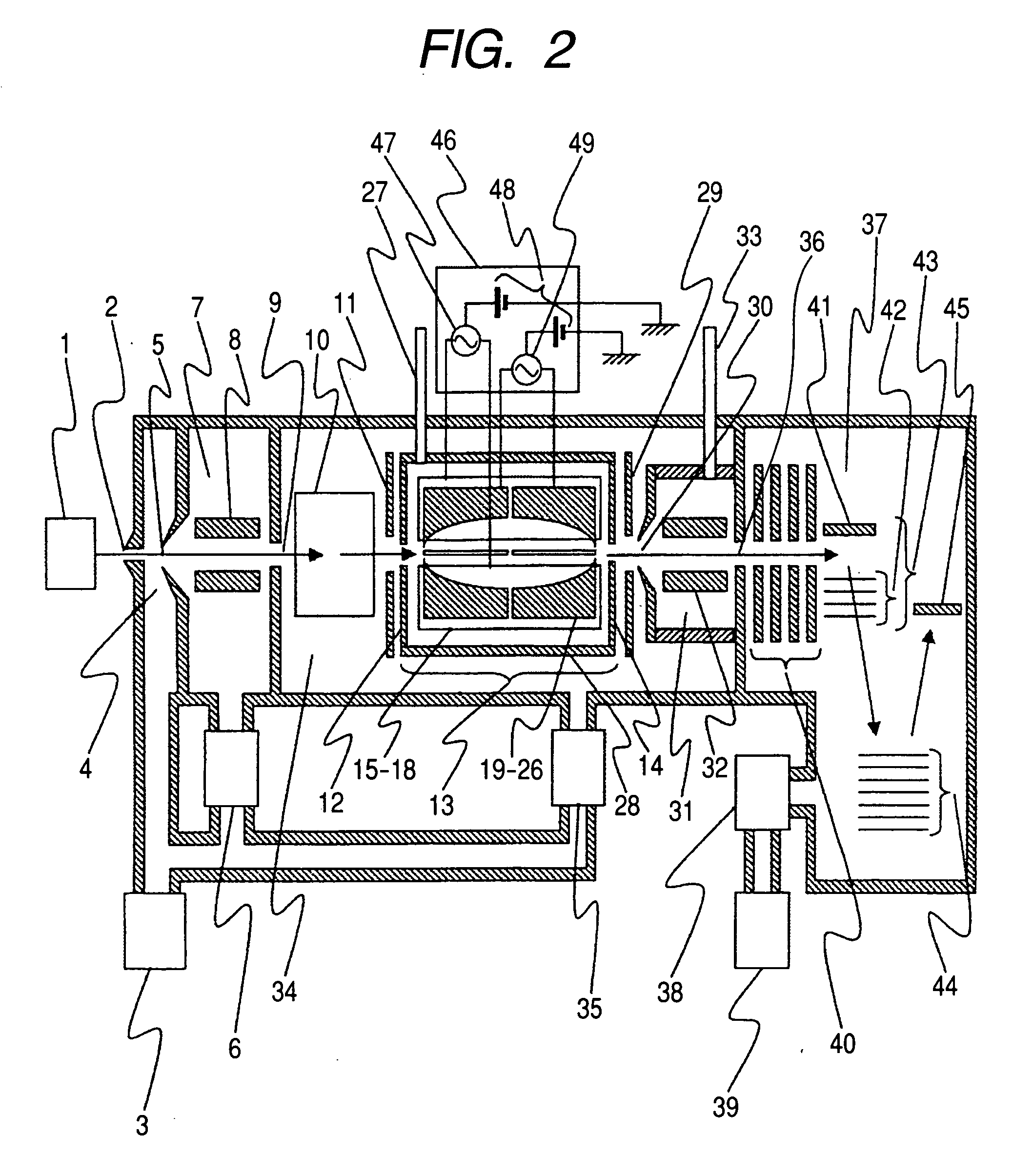
[0043]FIG. 2 shows a schematic composition of the quadrupole linear ion trap time-of-flight mass spectrometer in accordance with the present invention.
[0044]The ions generated in an ion source 1 pass through aperture 2, and are introduced into a first differential pumping region 4 evacuated to 100-500 Pa with a rotary pump 3. Then, ions pass through aperture 5 and are introduced into a second differential pumping region 7 evacuated with a turbo molecular pump 6. The second differential pumping region 7, in which multipole electrodes 8 are arranged, is maintained at pressures of about 0.3-3 Pa. A radiofrequency wave with a frequency of about 1 MHz, and a voltage amplitude of several hundred...
second embodiment
[0057]The second embodiment explains a system in which, in the linear ion trap with a multipole electrode, a sample ion for dissociation is isolated, resonantly excited and oscillated in the axial direction with a Supplemental AC voltage, and then collided with neutral gas and dissociated in the structure of quadrupole linear ion trap time-of-flight mass spectrometer.
[0058]In the embodiment, a system is explained in which ions are resonantly excited, and oscillated with a Supplemental AC voltage, and all the ions except the sample ion for dissociation are ejected out of a linear ion trap, and then the sample ion is dissociated.
[0059]Although the configuration of spectrometer in the present embodiment is nearly the same as that shown in FIG. 2, the sample ion isolation unit 10 is not necessarily required, since the sample ion for dissociation can be isolated in the quadrupole linear ion trap 13. Since the voltage application methods are different from those in the first embodiment, t...
third embodiment
[0067]The third embodiment shows a system in which, in the structure of quadrupole linear ion trap time-of-flight mass spectrometer, ions are resonantly excited and oscillated in the axial direction with a Supplemental AC voltage, so that all the ions except the one for dissociation are ejected out of the linear ion trap, and then the ion for dissociation is made to dissociate.
[0068]Although the configuration of spectrometer in the present embodiment is nearly the same as that shown in FIG. 2, a sample ion isolation unit 10 is not necessarily required since the sample ion for dissociation can be isolated in the quadrupole linear ion trap 13. Although the voltage applying method is nearly the same as that shown in FIG. 3, since the operating sequence is different from those in the embodiment 1 and 2, the sequence is explained in detail in the following.
[0069]Referring to FIG. 9 the operating sequence is explained of each electrode in the case of performing isolation and dissociation ...
PUM
 Abstract
Description
Claims
Application Information