
Antireflection film forming method, and substrate treating apparatus

a technology of antireflection film and substrate, applied in the field of antireflection film forming method and substrate treating apparatus, can solve the problems of pattern collapse and hamper the maintenance of certain essential characteristics and achieve the effects of increasing the adhesion energy in water, and reducing the hydrogen bonding component of surface energy of the antireflection film

Inactive Publication Date: 2007-08-09
SOKUDO CO LTD
View PDF0 Cites 0 Cited by
  • Summary
  • Abstract
  • Description
  • Claims
  • Application Information

AI Technical Summary

Benefits of technology

[0008] This invention has been made having regard to the state of the art noted above, and its object is to provide antireflection film forming methods and substrate treating apparatus for improving adhesion between antireflection film formed on a substrate and resist film formed on the surface of the antireflection film, without impairing the characteristics of the antireflection film, thereby to inhibit pattern collapse.
[0009] The above object is fulfilled, according to this invention, by an antireflection film forming method for forming antireflection film on a substrate in advance of applying a resist solution to the substrate, the method comprising performing surface modifying treatment of the antireflection film for reducing a hydrogen bonding component of surface energy of the antireflection film formed on the substrate.
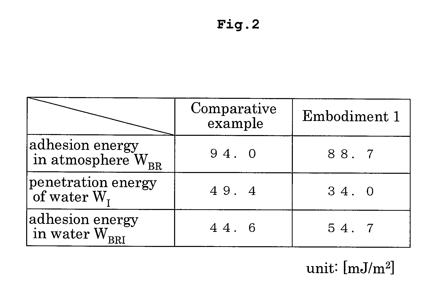
[0010] According to the invention, the surface modifying treatment reduces the hydrogen bonding component of surface energy of the antireflection film, thereby increasing the adhesion energy in water of the antireflection film and resist film. This inhibits a resist pattern collapse. The chemical composition of the antireflection film itself is not changed by the surface modifying treatment. Thus, the essential characteristics of the antireflection film are maintained intact.

Problems solved by technology

With an increasingly refined structure today, resist patterns have large aspect ratios, resulting in an inconvenience of causing a pattern collapse in time of development.
However, this measure requires a change in the composition of antireflection film, which hampers maintenance of certain essential characteristics of the antireflection film such as reflection preventing performance.

Method used


Image

  • Antireflection film forming method, and substrate treating apparatus
  • Antireflection film forming method, and substrate treating apparatus
  • Antireflection film forming method, and substrate treating apparatus

Examples


first embodiment

[0036] Embodiment 1 of this invention will be described hereinafter with reference to the drawings.

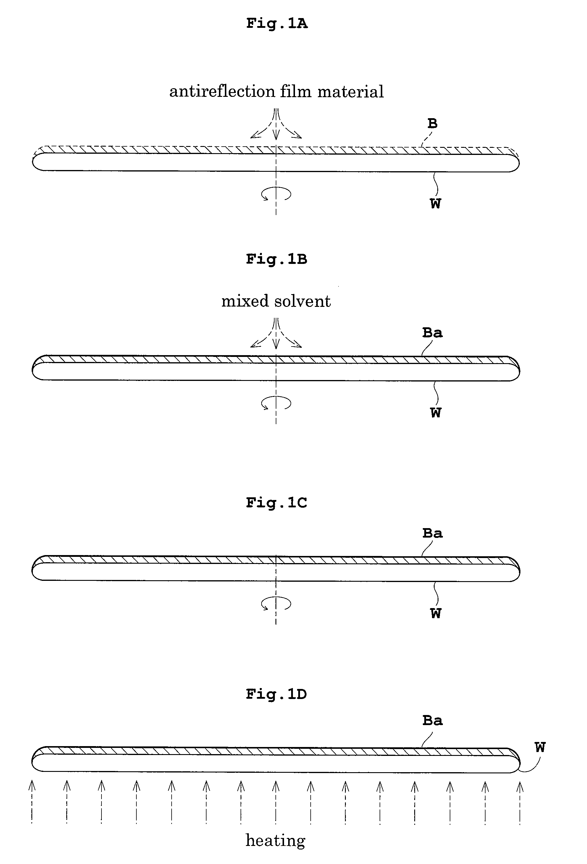
[0037]FIGS. 1A-1D are schematic views showing steps of treating a substrate by an antireflection film forming method in Embodiment 1.

[0038]

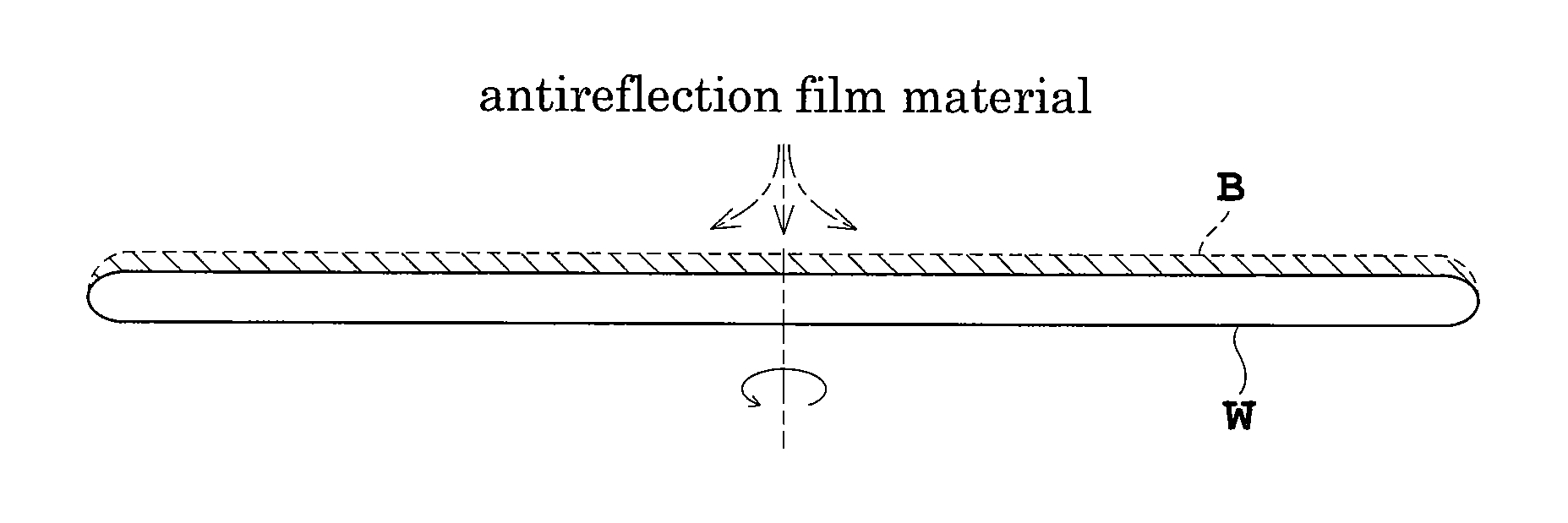
[0039] As shown in FIG. 1A, an organic antireflection film material is supplied to the upper surface of a wafer W under treatment while the wafer W is spun in horizontal posture (spin coating). The antireflection film material spreads over the entire surface of wafer W, forming an antireflection film B on the wafer W. Subsequently, the supply of the antireflection film material is stopped.

[0040] Then, as shown in FIG. 1B, while the spin of wafer W is continued, a mixed solvent of hexamethyldisilazane (hereinafter called simply HMDS) and xylene is supplied in a predetermined quantity to the upper surface of antireflection film B. This reduces a hydrogen bonding component of surface energy of antireflection film B. In this specification, this step ...

second embodiment

[0059] Embodiment 2 of this invention will be described hereinafter with reference to the drawings.

[0060]FIGS. 3A-3D are schematic views showing steps of treating a substrate by an antireflection film forming method in Embodiment 2. Treating steps similar to those in Embodiment 1 will be described only briefly.

[0061]

[0062] As shown in FIG. 3A, an antireflection film material is spin-coated on the wafer W under treatment.

[0063]

[0064] As shown in FIG. 3B, the wafer W is maintained in the spinning state to dry antireflection film B coating the wafer W. No surface modifying treatment is performed during the drying step.

[0065]

[0066] As shown in FIG. 3C, the wafer W is subjected to heat treatment.

[0067]

[0068] Further, as shown in FIG. 3D, the wafer W is heat-treated while supplying a gas including HMDS to the upper surface of antireflection film B coating the wafer W (which corresponds to the surface modifying treatment in this invention). As a result, the antireflection film B is mo...

third embodiment

[0076] Next, a substrate treating apparatus suited to implement above Embodiments 1 and 2 will be described with reference to the drawings. FIG. 4 is a schematic plan view of the substrate treating apparatus.

[0077] The substrate treating apparatus in Embodiment 3 is constructed for forming antireflection film and resist film on wafers W under treatment, and performing chemical treatment such as development on exposed wafers W.

[0078] The substrate treating apparatus in this embodiment includes an indexer block 1 for fetching wafers W from cassettes C each containing a plurality of wafers W in multiple stages, and depositing wafers W in the cassettes C, an antireflection film forming block 2 for forming antireflection film on the wafers W, a resist film forming block 3 for forming resist film on the wafers W, a developing block 4 for developing the wafers W, and an interface block 5 for delivering and receiving the wafers W to / from an exposing apparatus (e.g. stepper) STP which is a...


PUM

PropertyMeasurementUnit
surface energyaaaaaaaaaa
timeaaaaaaaaaa
adhesion energyaaaaaaaaaa

Abstract

A substrate is first spin-coated with an antireflection film material is carried out to the substrate to form antireflection film on the substrate. Next, a mixed solvent of HMDS and xylene is supplied in a predetermined quantity to the upper surface of the antireflection film, and is spin-dried in this state. The mixed solvent effects surface modifying treatment to reduce a hydrogen bonding component of surface energy of the antireflection film. Subsequently, the substrate receives heat treatment. This completes formation of the antireflection film on the substrate. As a result, the antireflection film has increased adhesion energy in water with respect to resist film, without impairing essential characteristics of the antireflection film.

Description

BACKGROUND OF THE INVENTION [0001] (1) Field of the Invention [0002] This invention relates to antireflection film forming methods and substrate treating apparatus for forming antireflection film on semiconductor wafers, glass substrates for liquid crystal displays, glass substrates for photomasks, or substrates for optical disks (hereinafter called simply “substrates”). More particularly, the invention relates to a technique for increasing adhesion energy in a liquid between antireflection film and resist film formed on the surface of the antireflection film. [0003] (2) Description of the Related Art [0004] In photolithography, BARC (Bottom Anti-Reflection Coating) method is used to form antireflection film under photoresist film in order to reduce standing wave and halation occurring in time of exposure. In order to use this BARC method, a substrate treating apparatus includes an antireflection film forming block along with a resist film forming block and a developing block. A sub...

Claims


Application Information

Patent Timeline
Patent Type & Authority Applications(United States)
IPC IPC(8): G02B1/10
CPCG03F7/091G02B1/111
Inventor TAMADA, OSAMUSANADA, MASAKAZUGOTO, TOMOHIRO
Owner SOKUDO CO LTD
Learn More