
Method and system for process gas entrainment and mixing in a kiln system

Inactive Publication Date: 2007-08-09
HOLCIM
View PDF17 Cites 23 Cited by
  • Summary
  • Abstract
  • Description
  • Claims
  • Application Information

AI Technical Summary

Benefits of technology

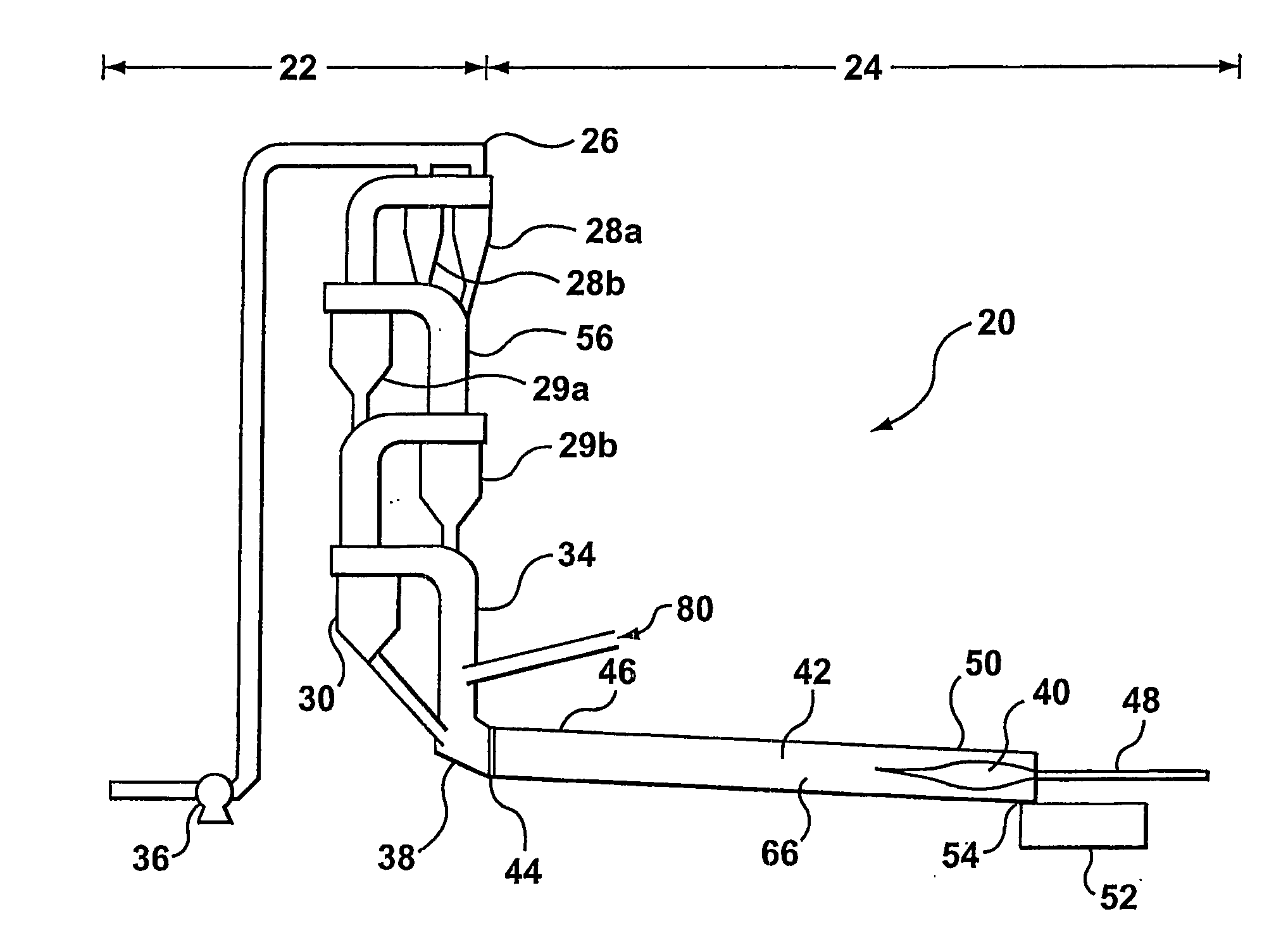
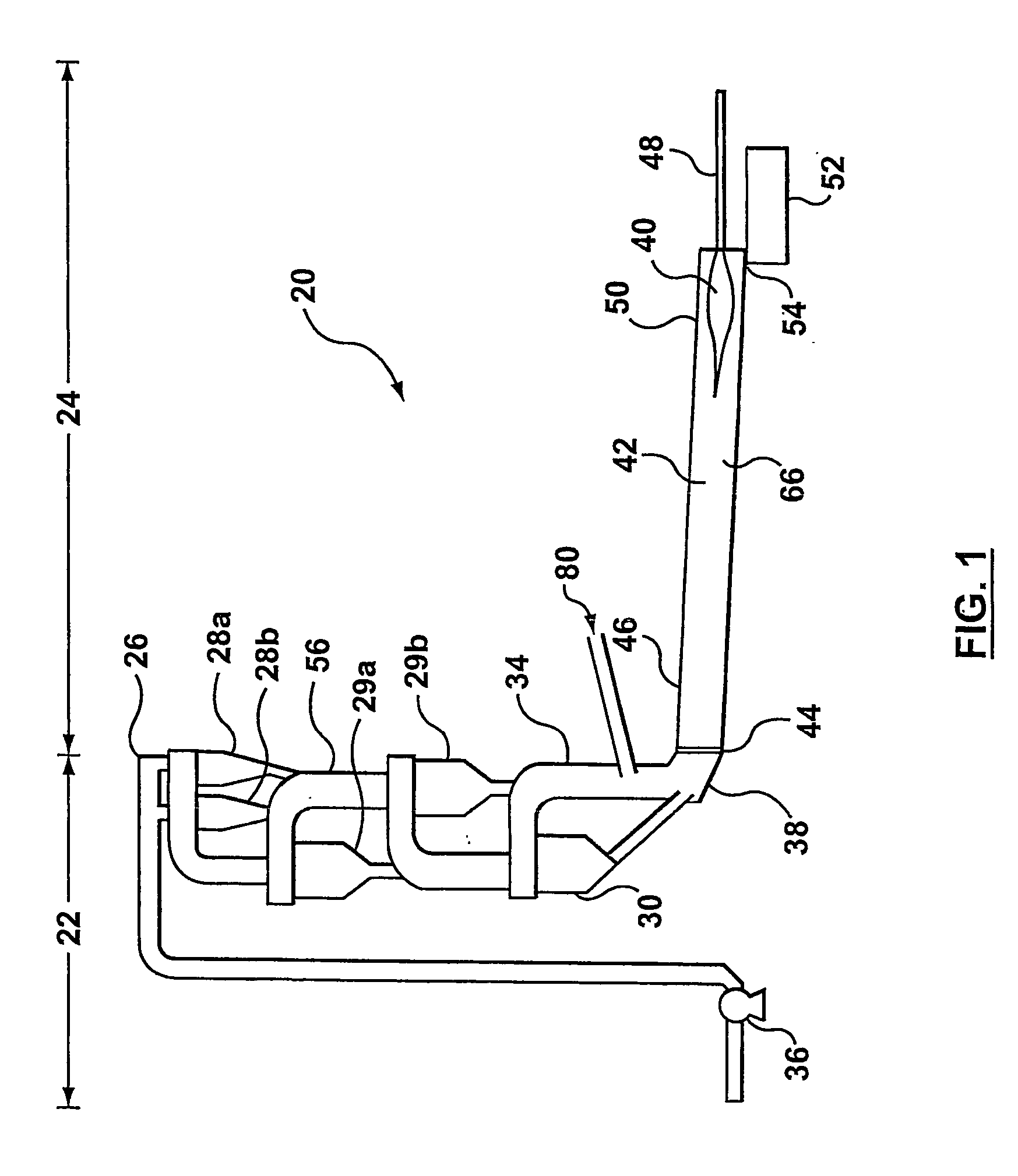
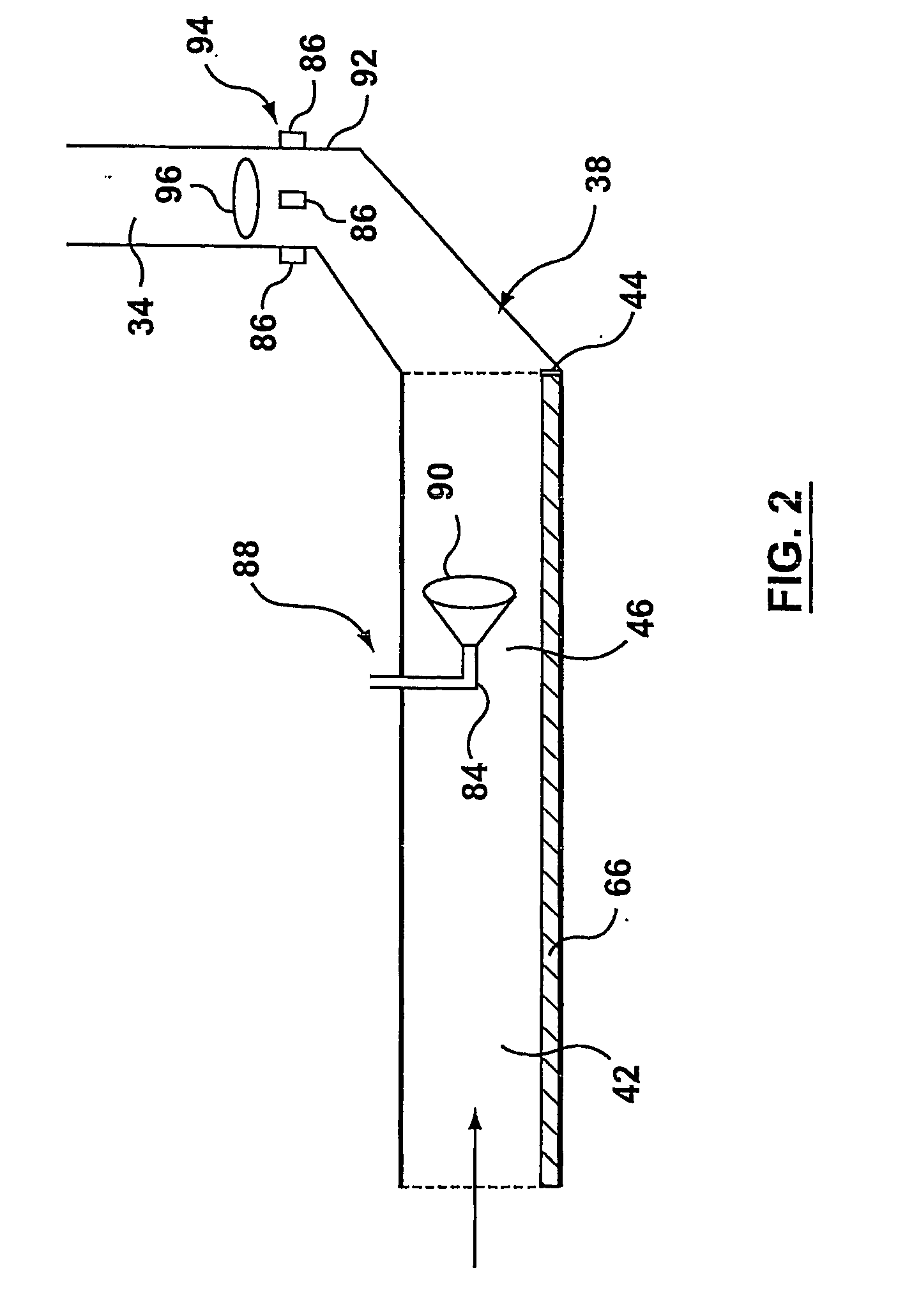
[0031] In particular, an embodiment of the invention relates to a method and system for adding or injecting suitably-directed high momentum swirling turbulent gas to dust-laden stratified process gas at approximately 850 to 1400° C. to eliminate stratification and improve mixing of both process gases and suspended solids. The gas injection serves to enhance the contact of reacting materials, such as residual fuel and available oxygen, and further serves to improve the completion of reactions, such as combustion of the fuel and the transfer of heat to the raw meal / kiln feed / hot meal.
[0032] The projected benefits of the embodiments of the invention include increased fossil fuel substitution, lower carbon monoxide emissions lower emissions of oxides of nitrogen, ammonia and dioxins, higher levels of petroleum coke use and increased clinker output.
[0035] In either of the above embodiments, the injector may be provided with swirl vanes and, in a preferred case, swirl vanes having an angle of approximately 10 to 35 degrees. As an alternative or in combination with the swirl vanes, the injector may also be provided with flare diffusers and / or a bluff body to enhance the entrainment. Preferably, the flare diffusers are at approximately 5 to 20 degree half angles.
[0040] In the above embodiment, the injectors may be provided with swirl vanes and, in a preferred case, swirl vanes having an angle of approximately 10 to 35 degrees. As an alternative or in combination with the swirl vanes, the injectors may also be provided with flare diffusers and / or a bluff bodies to enhance the entrainment. Preferably, the flare diffusers are at approximately 5 to 20 degree half angles.
[0048] In a preferred case of the above two embodiments, the method may include imparting swirl to the injection gas as it enters the housing, for example, by using swirl vanes. Alternatively or in combination, the turbulent flow and entrainment may be enhanced by using flare diffusers and / or bluff bodies.
[0053] The mixing provided by the gas injection results in improved combustion of lump solid fuels (such as tires, wood and plastics) to encourage full, controlled and non-polluting combustion with energy release. The mixing provided by the gas injection also improves gas-to-particle heat transfer and makes better use of available oxygen in a kiln system.

Problems solved by technology

The following discussion will focus on preheater kiln systems however, similar processes occur in and similar difficulties may also arise in long kiln systems.
These other chemical species can enter in quantities that adversely influence conditions within the kiln system.
A drawback to the use of either a conventional or an alternative fuel (before processing “raw fuel”), is often the need for prior expensive and energy-intensive preparation, examples of such would be the fine grinding of solids or the atomization of liquids.
Various difficulties arise in the operation of conventional kiln systems, including pre-heater kiln systems when using either traditional fossil fuels prepared according to conventional methods and / or alternative fuels prepared by less conventional means.
As a consequence, there may be limitations on the amount of one or more fuels, in a given state of preparation, that can be supplied to a precalciner, gas riser duct or upper end of a kiln while still maintaining suitable clinkering conditions at the lower / outlet end of the kiln system.
Conventional preheater kiln systems may have one or more of the following difficulties: (a) a build-up of solid material in the system resulting in either a partial or complete blockage; (b) an increased generation of one or more pollutants, such as NOx (or a limitation upon the degree of abatement possible within the process); (c) an increase in energy consumption per tonne of product; and / or (d) a reduced output rate.
Several of the above noted difficulties have the additional disadvantage of limiting the possibilities for reducing consumption of prime fossil fuels with a consequent accompanying limitation of the scope for reducing the generation and emission of greenhouse gases, such as carbon dioxide.
Implementing such solutions, however, is often not cost-effective.
Higher exit gas temperatures would suggest that the extra energy has not all been efficiently applied to heat the solid materials, but has instead been wasted in creating and heating the gases.
Techniques intended to promote the beneficial mixing of gases in kiln systems are known, however, the levels of momentum and swirl involved are typically not large enough to be completely effective aerodynamically.

Method used


Image

  • Method and system for process gas entrainment and mixing in a kiln system
  • Method and system for process gas entrainment and mixing in a kiln system
  • Method and system for process gas entrainment and mixing in a kiln system

Examples


example

[0142] A SAS system as described above has been successfully applied in a 4500 tpd off line calciner kiln system. The kiln was 84 m long and 5.2 m in diameter; the calciner had a volume of 350 m3 with a gas residence time of 2.5-3.0 secs.

[0143] Without the SAS, even at high oxygen levels that cause a drop in output rate, the calciner had significant CO problems, resulting in levels of up to 1500 ppm CO at the stack (corresponding to 10,000 ppm ex calciner at normal O2 levels of 2-3%). The high CO was thought to come from poor mixing, hence SAS was tried as a solution to the problem.

[0144] SAS was installed with a 10,000 Nm3 / hr fan, which could supply at 2500 mm water gauge with the aim of resolving problems of CO generation due to poor mixing conditions. The system had 4 swirler flow injectors with 20 degree swirl vanes injecting on to a circle of 0.3 R radius (R=calciner duct radius) and 2 swirler flow injectors directed on to a 0.5 R circle (in the same plane) in a counter rotat...


PUM

PropertyMeasurementUnit
Temperatureaaaaaaaaaa

Abstract

A method and system for mixing process gas flow by adding or injecting suitably-directed high momentum turbulent gas into dust-laden stratified process gas flow at approximately 850 to 1400° C. to entrain the process gas flow such that stratification is reduced and mixing of both gases and suspended solids is improved. The jet entrainment of the process gas flow by appropriate injection of gas serves to enhance the contact of reacting materials, such as residual fuel and available oxygen, and further serves to improve the completion of reactions, such as combustion of the fuel and the transfer of heat to the raw material / kiln feed.

Description

FIELD OF THE INVENTION [0001] The present invention relates to a method and system for process gas entrainment and mixing in a kiln system. More particularly, it relates to a method and system in which a process gas flow is entrained by injected gas causing mixing of the process gas flow and facilitating the combustion and removal of chemical species present in the process gas flow during combustion in a kiln system. BACKGROUND OF THE INVENTION [0002] Kiln systems are known for processing cement clinker and various metallic and non-metallic minerals such as iron ore and lime. In this application, the text focuses on kiln systems for producing cement clinker, however, it will be understood by one of skill in the art that the concepts presented may have application in other types of kiln systems. [0003] Cement clinker is the material that, when finely powdered forms cement, which is mixed with water and inert materials to form concrete and mortar. Cement clinker is conventionally prod...

Claims


Application Information

Patent Timeline
IPC IPC(8): F27B15/00B01F23/10F27B7/36F27D7/04
CPCF27D7/04F27B7/362
Inventor LOWES, THOMAS MCQUIGGIN
Owner HOLCIM
Learn More