[0021] The heat-generating
cement body and heat-generating
cement tile that are obtained from the method of manufacturing the heat-generating cement body and heat-generating
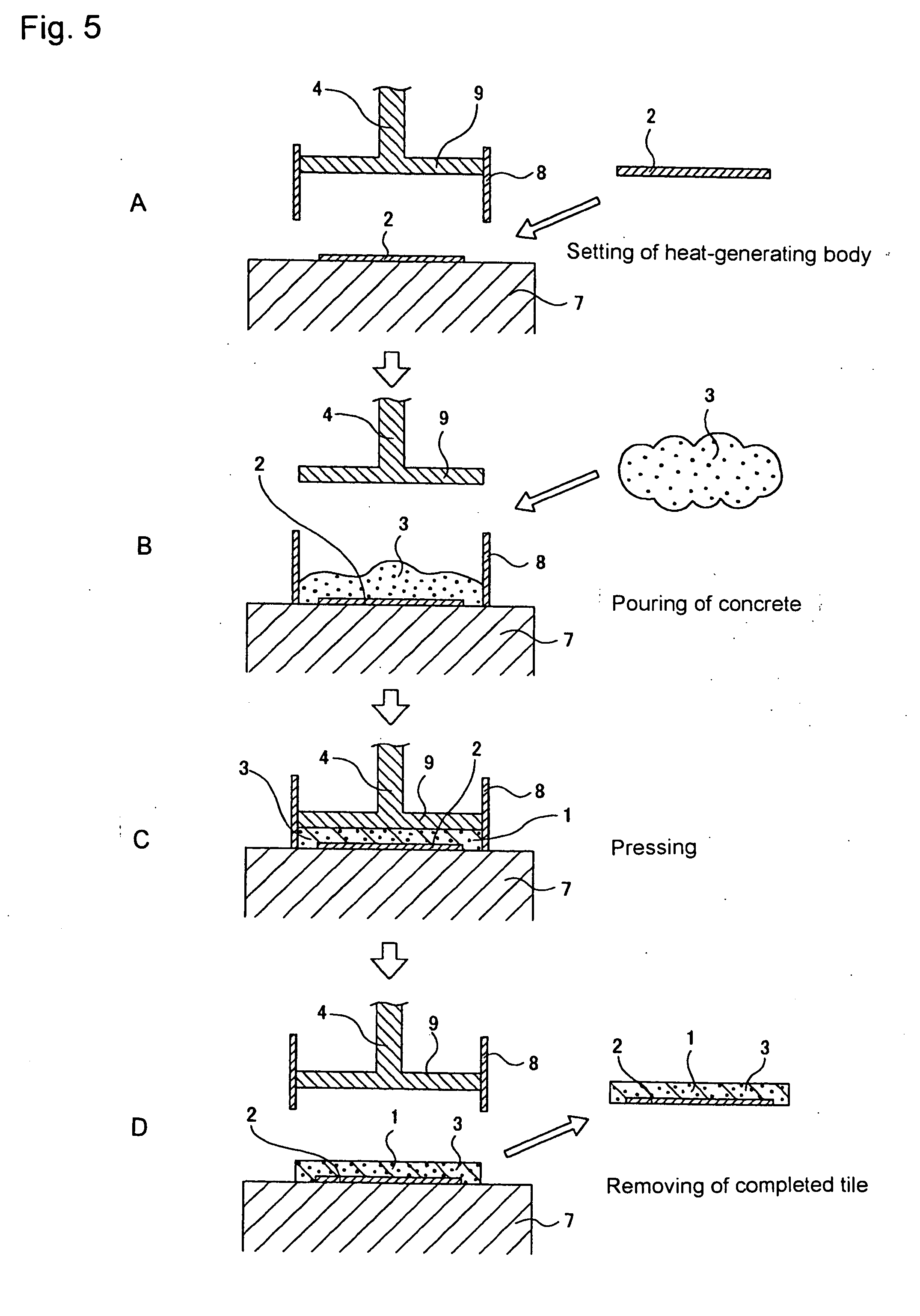
cement tile of this invention described above are constructed such that carbon material is contained in un-hardened concrete or
mortar and pressed by a high-pressure press to remove
moisture and form a desired shape. Therefore, it is possible to sufficiently press the moisture and air from the un-hardened concrete or
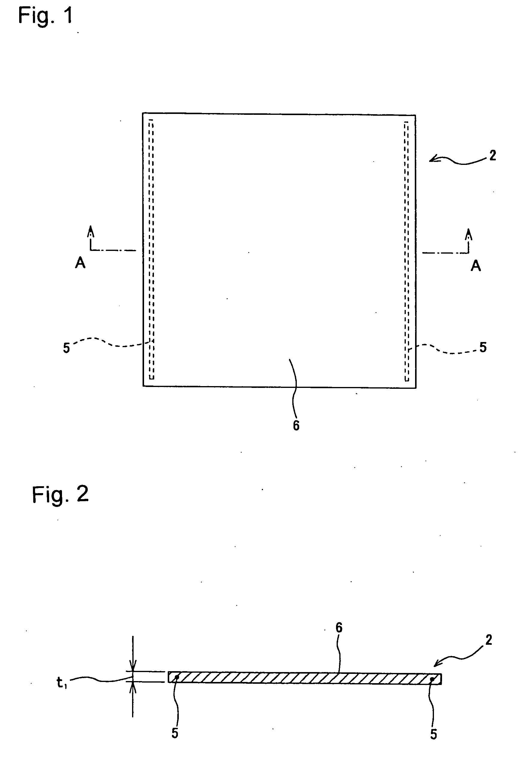
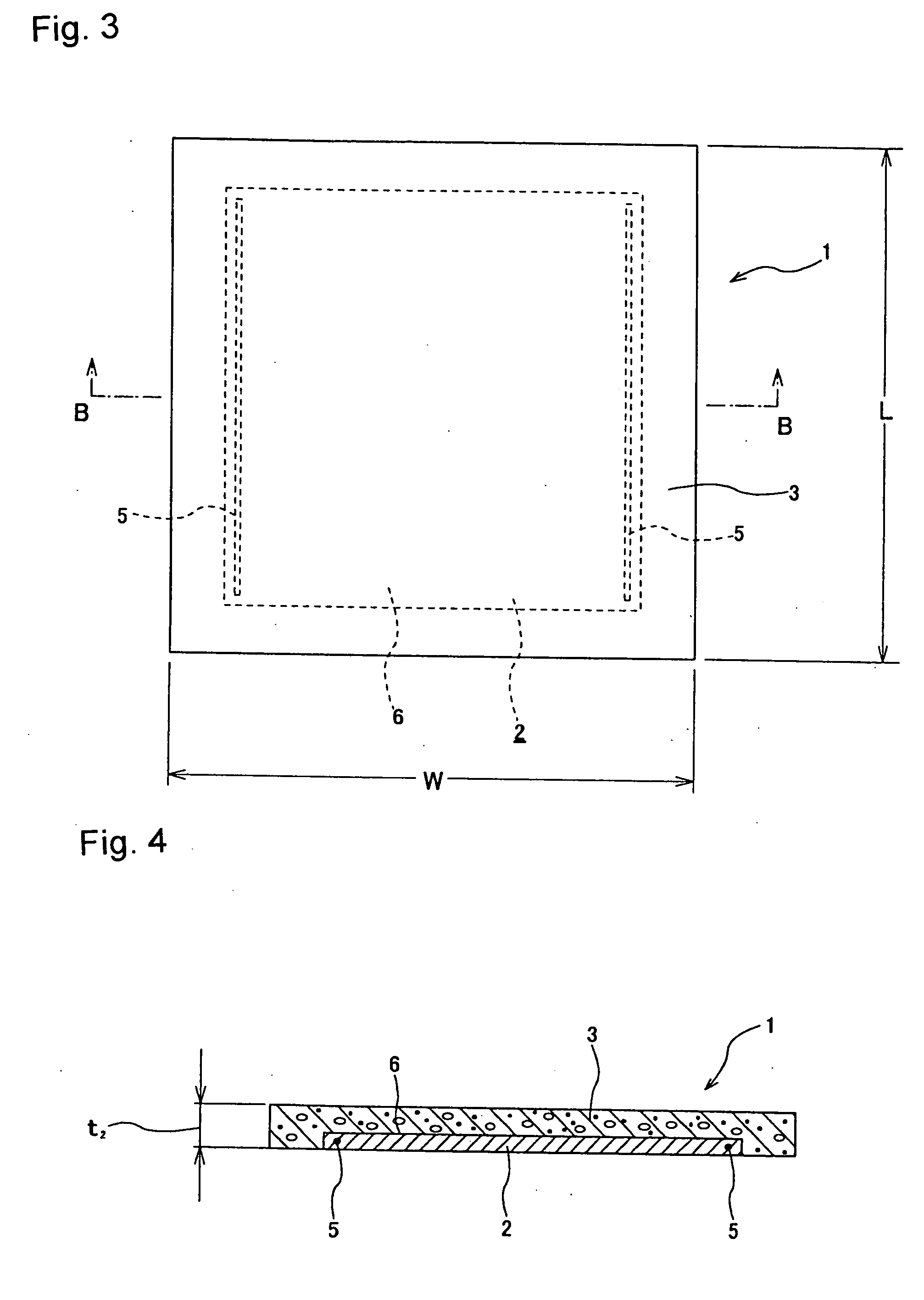
mortar, and to improve the distribution density of the carbon material. Also, it is possible to uniformly mix the carbon material inside the heat-generating cement body. Therefore, contact among the carbon material is not hindered, and it is possible to more easily and effectively have contact among some carbon material. Moreover, by adjusting the ratio of the amount of carbon material contained in heat-generating cement body, it is possible to more effectively have contact among particle-form or powder-form carbon material, and to adjust the electrical resistance inside the heat-generating cement body to a specified value. As a result, by passing current through the inside of the heat-generating cement body by way of electrodes that are located on both sides of the heat-generating cement body, it is possible to heat the heat-generating cement body and heat-generating
cement tile to a desired temperature. Furthermore, in the case of this invention, this kind of construction is stably obtained. Also, since it is possible to uniformly mix the carbon material inside the heat-generating cement body, it becomes possible to uniformly heat the heat-generating cement body, so the energy efficiency is good. Moreover, it is possible to improve strength, while at the same time maintain good
conductivity inside.
[0022] To explain this in more detail, conventionally when mixing and dispersing carbon material in cement, due to the
surface tension of the carbon material, it was difficult to uniformly disperse the carbon material in un-hardened concrete or
mortar with just normal mixing. For example, when dispersing carbon material in a
polymer, by adding a dispersing agent (interface active material) or the like, uniform dispersion becomes possible. However, in the case of obtaining the heat-generating cement body of this invention, it is not possible to use this kind of dispersing agent to uniformly disperse the carbon material, so it is difficult to uniformly disperse the carbon material in un-hardened concrete or mortar by only normal mixing. Also, as a heat-generating element, in order to obtain the necessary internal
conductivity, it is necessary that the particles of carbon material are continuous and come in contact with each other inside the heat-generating element. Therefore, it is feasible that as a means to accomplish this, the ratio (content) of the amount of carbon material contained in the un-hardened concrete or mortar be increased. However, increasing the amount of carbon material contained may become a cause for inviting insufficient strength of this heat-generating element made of concrete or mortar.
[0023] On the other hand, in the case of the heat-generating cement body of this invention, particle-form or powder-form carbon material is contained in the un-hardened concrete or mortar, and it is pressed by a high-pressure press to remove moisture. Therefore, when applying pressure and removing moisture, due to the
osmotic pressure (drainage
osmotic pressure) that occurs when discharging moisture from the un-hardened concrete or mortar, it becomes easy for uniform dispersion phenomenon of the carbon material to occur. As a result, it is feasible that it will become easy to uniformly distribute the carbon material inside the heat-generating cement body. Also, by becoming easy to uniformly distribute carbon material inside the heat-generating cement body, it is possible to keep the amount of carbon material contained needed for obtaining good
conductivity sufficiently low. In other words, it becomes easy to obtain good conductivity even when the amount of carbon material contained is kept low. Thus, by keeping low the amount of the carbon material contained, it becomes easy to increase strength of the heat-generating cement body. Therefore, with this invention, it is possible to increase strength while maintaining good conductivity.
[0024] Next, the testing that was performed to confirm the effect of the invention will be explained. First, as a premise to this testing, it is known that when using a heat-generating tile comprising a heat-generating cement body as a sidewalk tile with snow-removal function, it is preferable that the heat-generating cement body be heated using about 20 to 400 W. Also, using the relational expression (
Heating Power) W=(
Voltage) V2 / (Resistance) R, it is known that in order to heat the heat-generating cement body with 20 W or greater by applying a
voltage of 100 V, it is necessary to lower the resistance value of the heat-generating cement body to 533 Ω or less. Also, in order to heat the heat-generating cement body with 40 W or greater by applying a
voltage of 100 V, it is necessary to lower the resistance value of the heat-generating cement body to 250 Ω or less. In this way, using the heat-generating cement body applied with a specified
voltage, it is known that in order to obtain the desired
heating power or more, it is effective to keep the resistance value of the heat-generating cement body low. However, when the amount of carbon material contained is increased in order to lower the resistance value, it becomes difficult to sufficiently maintain the strength of the heat-generating cement body. For example, when the amount of carbon material contained exceeds 10%, the strength of the heat-generating cement body is insufficient.
[0025] On the other hand, when performing testing using a heat-generating cement body having the same construction as that of this invention, it was possible to make the resistance value of the heat-generating cement body 533 Ω even when the amount of carbon material contained in the cement was sufficiently low at approximately 1.3 weight %, and it was possible to obtain a
heating power of 20 W when a 100 V voltage was applied. Moreover, it was possible to make the resistance value of the heat-generating cement 250 Ω even when the amount of carbon material contained in the cement body was sufficiently low at approximately 1.8 weight %, and it was possible to obtain a
heating power of 40 W when a 100 V voltage was applied. In this way, the heat-generating cement body of this invention was obtained by mixing particle-form or powder-form carbon material in un-hardened concrete or mortar at a specified ratio, and then pressing it with a high-pressure press to remove moisture, so it was possible to make the amount of carbon material contained low enough to obtain good conductivity, and it was possible to confirm that strength was increased while maintaining good conductivity.
[0026] On the other hand, different from this invention, in the case in which heat-generating cement is obtained by mixing particle-form or powder-form carbon material in un-hardened concrete or mortar, and simply letting it harden (without pressing it with a high-pressure press to remove moisture), when the ratio of the amount of carbon material contained is less than 10%, it was found that it is not possible make the resistance value of the heat-generating cement body sufficiently low, and it was not possible to maintain both strength and good conductivity.

