Method and apparatus for stereoscopic display using column interleaved data with digital light processing

a stereoscopic display and digital light processing technology, applied in the field of stereoscopic display using, can solve the problems of increased complexity, high cost of multiple display devices, and inability to regulate color of chips, so as to avoid noticeable flicker, reduce the cost of multiple display devices, and improve the effect of stereoscopic display

Inactive Publication Date: 2007-08-23
DIVELBISS ADAM W +1
View PDF7 Cites 87 Cited by
  • Summary
  • Abstract
  • Description
  • Claims
  • Application Information

AI Technical Summary

Benefits of technology

[0040] There are several brands of off-the-shelf DLP projection systems that have been found to support a form of “page-flipped” 3D output without any modifications. To view stereoscopic 3D images with such projectors, a pair of liquid crystal shutter glasses may be synchronized to the video input source or to the RGB computer input source. The major shortcoming of this solution is that the maximum input frame rate for the RGB computer input is typically 85 Hz (42.5 Hz per eye) and is not high enough to avoid noticeable flicker. This fact is also true for the video input that is fixed at around 60 Hz (30 Hz per eye). Another shortcoming is the fact that the flicker rate of the output is dependent on the input data frame rate.
[0041] The fundamental problem of stereoscopic imaging is the display of two perspective images in such a way that they appear simultaneous to an observer and in such a way that the each eye sees only the corresponding perspective image. There are many systems in existence that provided this capability for stereo viewing by various different methods. The problem solved by this invention is the display of high-quality 3D stereoscopic images using a digital micro-mirror based optical system. Further, the present invention provides a means and apparatus to interpolate 3D image data from any input signal resolution to the display resolution without corruption due to the mixing of left-right perspective image data. All major stereoscopic data formats are supported. Further the present invention provides a system whereby 3D image decoding may be accomplished through one of three different decoding methods including passive linearly polarized eyewear, passive circularly polarized eyewear, active shutter glass eyewear or color filter based glasses. In the preferred embodiment the user may switch between any of the 3D optical encoding methods by simply changing an external filter assembly.
[0042] Micro-mirror display technology (such as that developed by Texas Instruments) as discussed above is well suited to stereoscopic display because of its fast switching times and extremely low persistence compared to liquid crystal based display technologies such as polysilicon, DILA™ (digital image light amplifier), and LCOS (liquid crystal on silicon). These properties that are inherent to DMD technology help to reduce stereoscopic crosstalk (the observed light leakage between left and right perspective views) in ways that are not possible by other 3D methods. Further, unlike some other 3D methods this invention permits the operation of the 3D projector in both stereoscopic and non-stereoscopic modes without any physical hardware or software changes required in switching between the two viewing methods. In addition to the 3D enhancements to DMD projectors, one aspect of the invention also has the capability of enhancing the brightness of 3D projection systems. This benefit is derived from the cholesteric liquid crystal reflective coatings used on certain color wheels variations and used as a stand-alone polarization plate.
[0043] The invention has two main embodiments, a first called column switching and blanking and a second embodiment called column doubling. The first embodiment is a projector for displaying a stereoscopic image with projector using one or more digital micromirror devices positioned into a plurality of columns and rows. The projector itself includes a light source, an optical system, a video processing system and a data system for driving the micromirror devices. The data subsystem provides separate data to a plurality of column pairs of the micromirrors. The projector includes a stereoscopic control circuit having a first state of the control circuit for inputting a first eye view of the stereoscopic image and causing the micromirrors of a first column of each column pair to be in various on and off states during said first eye view of said stereoscopic image and for causing all of said micromirrors of a second column of each column pair to be in an off state during said first eye view of said stereoscopic image. A second state of the control circuit is used for inputting a second eye view of the stereoscopic image and causes the micromirrors of the second column of each column pair to be in various on and off states during the second eye view of the stereoscopic image and for causing all of the micromirrors of the first column of each column pair to be in an off state during the second eye view of said stereoscopic image.
[0044] The second embodiment is a projector for displaying a stereoscopic image with the projector using one or more digital micromirror devices positioned into a plurality of columns and rows The projector includes a light source, an optical system, a video processing system and a data system for driving said micromirror devices. The data subsystem provides separate data to a plurality of column pairs of the micromirrors. The projector includes a stereoscopic control circuit having a first state for inputting a first eye view of the stereoscopic image and causing each micromirror of each column pair to be in various but identical on and off states during said first eye view of said stereoscopic image. A second state of the control circuit for inputs a second eye view of the stereoscopic image and causes each micromirror of each column pair to be in various but identical on and off states during the second eye view of the stereoscopic image.
[0045] In any particular projector system the first eye view may represent either a left eye view or a right eye view and the second eye view is the other eye view.

Problems solved by technology

Since the DMD chip consists of thousands of tiny micro-electromechanical mirrors, the chip itself does not regulate color.
Second, it electromechanically latches the mirrors so that they cannot respond to changes in the address voltage until the mirrors are reset.
The designs represented by FIG. 8 and FIG. 9 are not the only possible ways in which a single chip DLP projection system can be configured.
The disadvantages of this system include added complexity due to the management of two DMD displays and retention of a mechanical color wheel filter system, among others.
The disadvantage of these systems is the higher cost of the multiple display devices and the more complicated optics.
The major shortcoming of this solution is that the maximum input frame rate for the RGB computer input is typically 85 Hz (42.5 Hz per eye) and is not high enough to avoid noticeable flicker.
The fundamental problem of stereoscopic imaging is the display of two perspective images in such a way that they appear simultaneous to an observer and in such a way that the each eye sees only the corresponding perspective image.

Method used


Image

  • Method and apparatus for stereoscopic display using column interleaved data with digital light processing
  • Method and apparatus for stereoscopic display using column interleaved data with digital light processing
  • Method and apparatus for stereoscopic display using column interleaved data with digital light processing

Examples


Embodiment Construction

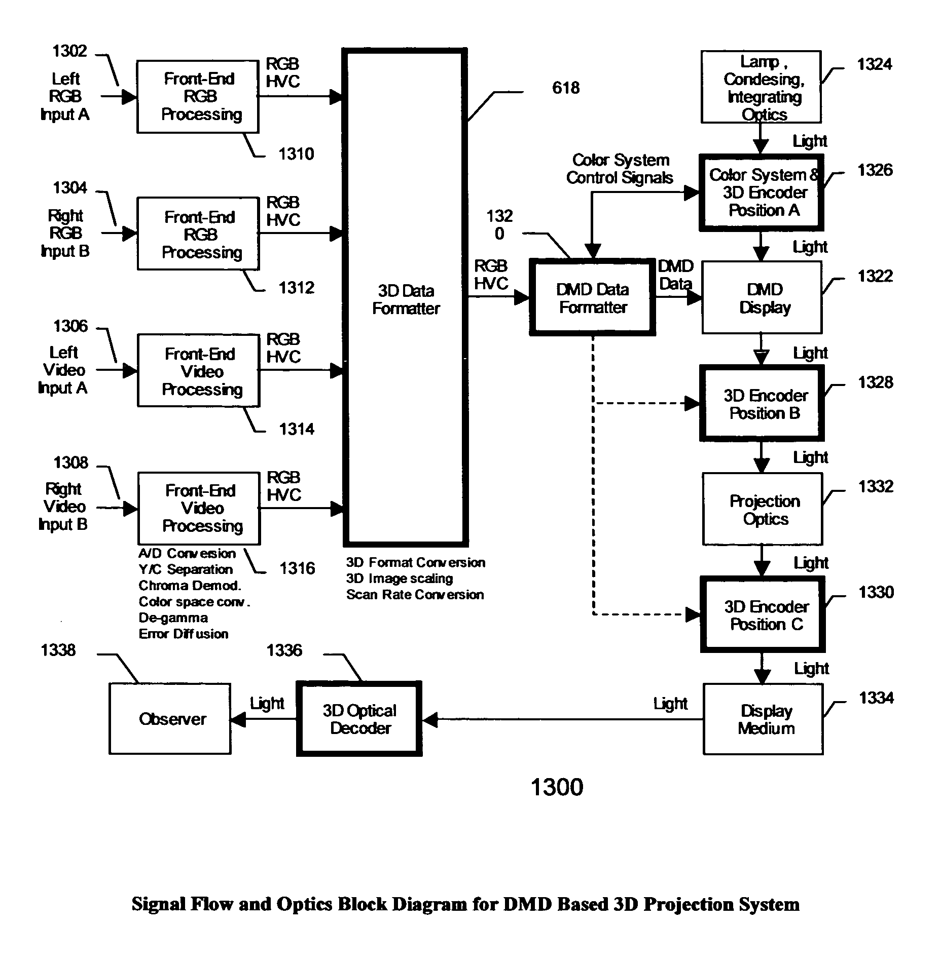
[0098] The fundamental problem of stereoscopic imaging is the display of two perspective images in such a way that they appear simultaneous to an observer and in such a way that the each eye sees only the perspective image that corresponds to it. There are many systems in existence that provided this capability for stereo viewing by various different methods. The problem solved by this invention is the display of 3D stereoscopic images using DMD based optical systems configured in several different ways including the following: Single chip DMD with 3-color wheel; Single chip DMD with 4-color wheel; Dual chip DMD with 2-color wheel; Dual chip DMD with 3-color wheel; and Three chip DMD systems.

[0099] For each system configuration above there are one or more methods by which stereoscopic 3D display can be achieved. Using the DMD technology from Texas Instruments offers several advantages over other 3D methods. Properties inherent in the DMD chip help to reduce crosstalk between the ey...


PUM


Abstract

The invention has two main embodiments, a first called column switching and blanking and a second embodiment called doubling. The first embodiment is a projector for displaying a stereoscopic image with projector using one or more digital micromirror devices positioned into a plurality of columns and rows. The projector itself includes a light source, an optical system, a video processing system and a data system for driving the micromirror devices. The data subsystem provides separate data to a plurality of column pairs of the micromirrors. The projector includes a stereoscopic control circuit having a first state of the control circuit for inputting a first eye view of the stereoscopic image and causing the micromirrors of a first column of each column pair to be in various on and off states during said first eye view of said stereoscopic image and for causing all of said micromirrors of a second column of each column pair to be in an off state during said first eye view of said stereoscopic image. A second state of the control circuit is used for inputting a second eye view of the stereoscopic image and causes the micromirrors of the second column of each column pair to be in various on and off states during the second eye view of the stereoscopic image and for causing all of the micromirrors of the first column of each column pair to be in an off state during the second eye view of said stereoscopic image. The second embodiment is a projector for displaying a stereoscopic image with the projector using one or more digital micromirror devices positioned into a plurality of columns and rows. The projector includes a light source, an optical system, a video processing system and a data system for driving said micromirror devices. The data subsystem provides separate data to a plurality of column pairs of the micromirrors. The projector includes a stereoscopic control circuit having a first state for inputting a first eye view of the stereoscopic image and causing each micromirror of each column pair to be in various but identical on and off states during said first eye view of said stereoscopic image. A second state of the control circuit for inputs a second eye view of the stereoscopic image and causes each micromirror of each column pair to be in various but identical on and off states during the second eye view of the stereoscopic image.

Description

CROSS REFERENCE TO RELATED APPLICATIONS [0001] The present application is related to a Provisional Application Ser. No. 60 / 239,664 filed on Oct. 12, 2000 entitled DLP Based 3D Projection System, to an International Application number PCT / US01 / 32087 filed on Oct. 12, 2001 entitled Digital Light Processing Based 3D Projection System and Method and to another Provisional Application Ser. No. 60 / 261,136 filed on Jan. 12, 2001 entitled Method and apparatus for stereoscopic display using digital light processing. All of these references are incorporated herein by this reference.BACKGROUND OF THE INVENTION [0002] Digital light processing (DLP)® technology from Texas Instruments Inc. has been proven to be a viable and reliable technology for use in data and multimedia image projection systems. The basis of the DLP technology is the Digital Micro-mirror Device (DMD) from Texas Instruments as described in U.S. Pat. No. 5,061,049 by Hornbeck issued on Oct. 29, 1991 and incorporated herein by r...

Claims


Application Information

Patent Timeline
Patent Type & Authority Applications(United States)
IPC IPC(8): G09G5/00G02B27/22G02B7/00G02B30/25G03B21/00G09G3/00G09G3/34H04N5/74H04N9/31H04N13/239
CPCG02B26/008H04N19/597G02B27/2207G02B27/225G02B27/2264G02B27/26G03B33/08G09G3/002G09G3/003G09G3/346G09G2310/0235G09G2320/0247H04N5/7458H04N9/3114H04N9/3188H04N9/3197H04N13/0003H04N13/0029H04N13/0037H04N13/0055H04N13/0059H04N13/0239H04N13/0285H04N13/0422H04N13/0427H04N13/0429H04N13/0431H04N13/0434H04N13/0438H04N13/0454H04N13/0459H04N13/0497H04N2005/7466G02B26/0833H04N13/337H04N13/341H04N13/194H04N13/189H04N13/324H04N13/332H04N13/334H04N13/363H04N13/10H04N13/286H04N13/15H04N13/365H04N13/359H04N13/239H04N13/139H04N13/398G02B30/23G02B30/24G02B30/25
Inventor DIVELBISS, ADAM W.SWIFT, DAVID
Owner DIVELBISS ADAM W
Why Eureka
Try Eureka