Apparatus for detecting information on object

a technology of objects and apparatus, applied in the direction of liquid/fluent solid measurement, machines/engines, instruments, etc., can solve the problems of difficult to achieve high signal-to-noise ratio, difficult to synchronize the optical system, and take a long time to obtain a two-dimensional image, etc., to achieve the effect of increasing accuracy and speed

Active Publication Date: 2007-08-23
CANON KK
View PDF26 Cites 71 Cited by
  • Summary
  • Abstract
  • Description
  • Claims
  • Application Information

AI Technical Summary

Benefits of technology

[0013]According to the present invention, an object is irradiated with the electromagnetic waves described above as a rectangular shaped beam. Information (such as transmission images or reflection images) on the object can thus be obtained at a relatively high speed without decreasing accuracy (such as image resolution).

Problems solved by technology

This scanning method, however, takes much time to obtain a two-dimensional image.
These methods require a complicated, less flexible optical system to synchronize pumping light and probe light.
In addition, a high signal-to-noise (S / N) ratio is difficult to achieve because the power of THz waves generated by photoconductive switching elements is generally on the order of submicrowatts.
Furthermore, the resolution of pulse light is limited because the light is typically susceptible to wavelength dispersion.
The above methods also have limited applications because they generally require a large, expensive apparatus with large power consumption, typified by a high-power femtosecond laser.
This is a bottleneck in popularizing the use of THz imaging in industry.
When pixels are simultaneously obtained, such an intensity distribution tends to degrade peripheral image quality.

Method used


Image

  • Apparatus for detecting information on object
  • Apparatus for detecting information on object
  • Apparatus for detecting information on object

Examples


first embodiment

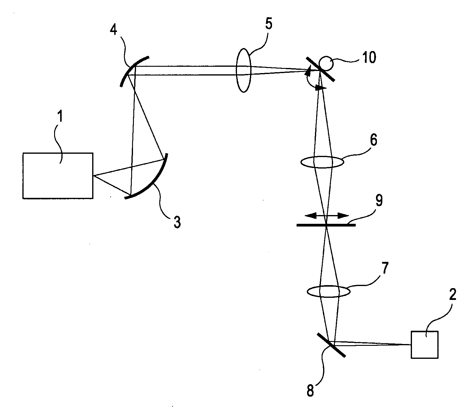
[0036]A first embodiment of the present invention will be described with reference to FIGS. 1 and 2. In the first embodiment of the present invention, a sample 9 is subjected to transmission imaging. In the first embodiment, electromagnetic waves output from the THz generator 1 are converted into a strip-like beam for increased S / N ratio, and a one-dimensional image is obtained by the THz detector 2. A two-dimensional image of the sample 9 is obtained by combining one-dimensional images obtained by scanning the sample 9 with the strip-like beam by moving the galvanometer mirror 10 in a rotational direction shown in FIG. 1. This fundamental system is as described above.

[0037]The array THz detector 2 used in this embodiment is a pyroelectric detector including a two-dimensional LiTaO3 array with 128 columns and 128 rows. The pixel pitch of the array is 100 μm. Although the two-dimensional array is used, one-dimensional images are obtained by image processing. The one-dimensional range...

second embodiment

[0041]A second embodiment of the present invention will be described. In the second embodiment of the present invention, as shown in FIG. 3, imaging is performed by detecting THz waves reflected by a sample 58. The system used for irradiation with THz waves is substantially the same as used in the first embodiment. Basically, the reflected waves are obliquely incident on the sample 58 for ease of detection. In this embodiment, the irradiation system includes a THz generator 50, two parabolic mirrors 52 and 53, and cylindrical lenses 54 and 55. A beam focused by the cylindrical lens 54 is reflected by a galvanometer mirror 59. The THz waves reflected by the sample 58 are made incident on an array THz detector 51, similar to that used in the first embodiment, by a cylindrical lens 56 and a reflective mirror 57, so that an image is obtained.

[0042]This system can be used for a THz inspecting apparatus 67 shown in FIG. 4 to inspect samples 66 being conveyed by a belt conveyor 65. This TH...

third embodiment

[0045]A third embodiment of the present invention will be described. In the third embodiment of the present invention, the type of object is roughly identified by detecting not only the transmittance or reflectance distribution of the object for THz waves, but also the phase shift distribution thereof, which depends on variations in dielectric constant. This can be achieved using an optical system including a delay optical system shown in FIG. 6. The transmission optical system used for a sample 94 in this embodiment is substantially the same as used in the first embodiment. That is, the irradiation system includes a THz generator 80, two parabolic mirrors 82 and 83, and cylindrical lenses 85 and 86. A beam focused by the cylindrical lens 85 is reflected by a galvanometer mirror 93. THz waves transmitted through the sample 94 are made incident on an array THz detector 81, similar to that used in the first embodiment, by a cylindrical lens 87 and a reflective mirror 88, so that an im...


PUM

PropertyMeasurementUnit
poweraaaaaaaaaa
diameteraaaaaaaaaa
lengthaaaaaaaaaa

Abstract

An apparatus for detecting information on an object includes an irradiating unit, a detecting unit, and an information-obtaining unit. The irradiating unit irradiates the object with electromagnetic waves as a rectangular shaped beam. The electromagnetic waves include a frequency component in (or range of) at least part of a frequency region of 30 GHz to 30 THz, and have variations in magnitude at intervals of 10−11 seconds or more or a temporally constant magnitude. The detecting unit detects the electromagnetic waves transmitted or reflected by the object through interaction therebetween. The information-obtaining unit obtains information on the object from information on the electromagnetic waves detected by the detecting unit.

Description

BACKGROUND OF THE INVENTION[0001]1. Field of the Invention[0002]The present invention relates to apparatuses and methods for detecting information on objects (samples), including image-obtaining apparatuses for observing the properties and shapes of objects using electromagnetic waves with high frequencies, mainly from millimeter waves to terahertz waves (30 GHz to 30 THz).[0003]2. Description of the Related Art[0004]Nondestructive sensing technology based on electromagnetic waves ranging from millimeter waves to terahertz (THz) waves (30 GHz to 30 THz, hereinafter simply referred to as THz waves or THz light) has recently been developed. The field of applications for electromagnetic waves in this frequency band under development includes: imaging technology for providing a safe alternative to radioscopy; spectroscopy for examining the properties of a substance, such as bound states, by determining the absorption spectrum and complex dielectric constant of the substance; analysis of...

Claims


Application Information

Patent Timeline
Patent Type & Authority Applications(United States)
IPC IPC(8): G01N23/00G01N21/3581G01N21/35G01N21/3586G01N22/00
CPCG01N22/00
Inventor OUCHI, TOSHIHIKO
Owner CANON KK
Why Eureka
Try Eureka