Isolated Fiber Optic Union Adapters

a technology of fiber optic cables and adapters, applied in the direction of optics, optical light guides, instruments, etc., can solve the problems of degrading the optical characteristics of the interface, the contact area of ferrules is highly susceptible to scratching, and the degradation of the other fiber terminations, so as to reduce the potential for damage, and the effect of low cos

Inactive Publication Date: 2007-08-23
KEWITSCH ANTHONYS
View PDF12 Cites 98 Cited by
  • Summary
  • Abstract
  • Description
  • Claims
  • Application Information

AI Technical Summary

Benefits of technology

[0023] This invention discloses isolated fiber optic union adapters that reduce the potential for damage to “critical” fiber optic terminations which are costly to repair. These adapters include a low cost internal fiber stub element within a precision alignment sleeve to prevent direct physical contact between the polished end faces of connectorized fibers while providing highly efficient optical coupling between the same connectorized fibers. The internal fiber stub element includes a length of single mode or multi-mode fiber(s) bonded within a pre

Problems solved by technology

Due to the delicate nature of polished glass surfaces, the ferrule contact areas are highly susceptible to scratching caused by contaminants trapped within the contact area.
Surface damage has the potential to degrade optical characteristics at the interface in the vicinity of the fiber optic core.
Furthermore, a single contaminated or damaged fiber/ferrule, if connected to other clean and undamaged fiber terminations, can degrade these other fiber terminations and propagate connector damage throughout the network.
The increased excess loss and reduced return loss can seriously compromise the network's performance.
With broadcast-type access networks, in which the optical signal is power split between as many as thirty-two users, the optical power budget of the network is strained and the impact of such damage is particularly significant.
In this situation, the cost to diagnose and repair damaged terminations may increase considerably depending on the physical location of the termination within the network.
For instance, damage to the connectorized drop cable within a customer's wall requires a costly service call and repair by an experienced technician.
Alternately, damage at the connector interface of a populated, high-density fiber p

Method used


Image

  • Isolated Fiber Optic Union Adapters
  • Isolated Fiber Optic Union Adapters
  • Isolated Fiber Optic Union Adapters

Examples


Embodiment Construction

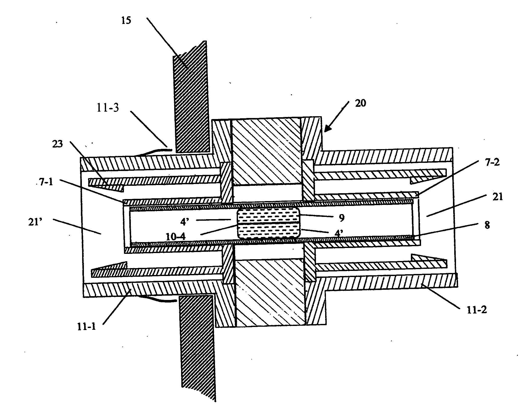
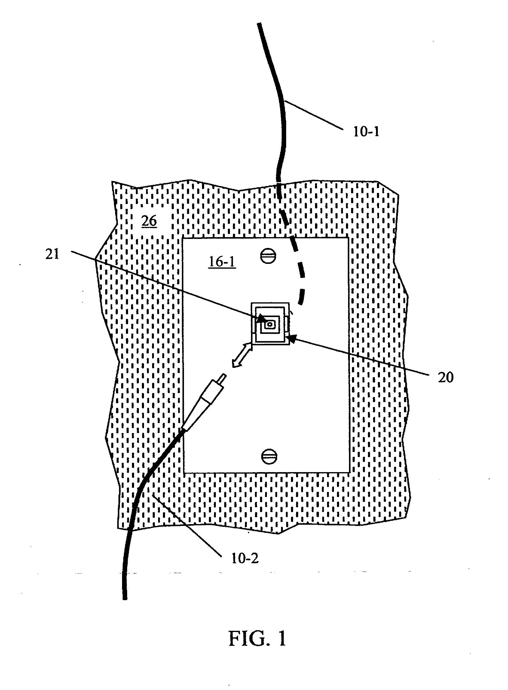
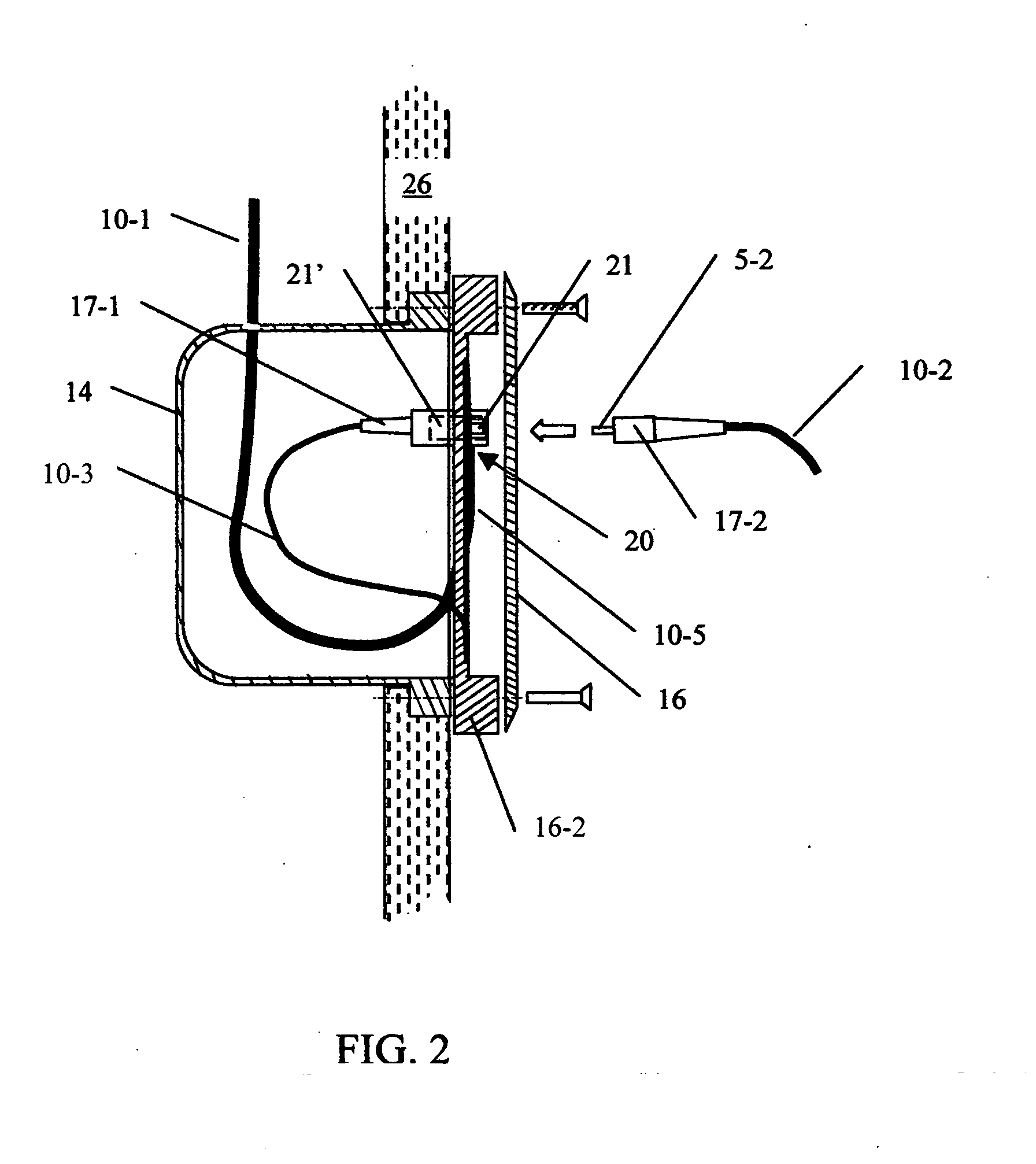
[0024]FIG. 1 illustrates a front view of an isolated fiberoptic union adapter 20 mounted to a wall plate 16 attached to wall surface 26. The connectorized end of a fiber optic patchcord 10-2 may be inserted into the front receptacle 21 of union adapter 20 to optically interface this patchcord 10-2 to a critical fiber optic drop cable 10-1 located within the plenum of a wall 26. FIG. 2 illustrates a side cutaway view of this same configuration, wherein the critical terminated end 17-1 of fiber 10-1 is inserted into the back receptacle 21′ of adapter 20. During the initial build-out of the fiber optic network, the jacket at the end of drop cable 10-1 is typically stripped to expose tight buffered optical fiber 10-3 of 900 micron diameter. An excess fiber length 10-5 is spooled after the fiber 10-1 is terminated with a polished connector 17-1, by use of a partial spool mandrel formed in the plastic injection molded interface plate 15. This polished connector 17-1 is produced either by ...


PUM


Abstract

Devices to enhance the reliability of optical networks and to reduce the cost of repair are disclosed in this invention. In particular, fiber optic union adapters with built-in protective isolation prevent a damaged, connectorized fiber optic cable from degrading other fiber optic terminations within the network should they be physically connected. The fiber optic union comprises a split sleeve with an interior channel and a fiber stub centrally located within the interior channel. The fiber stub prevents the ferrules of two different cables from making direct physical exchange but allows them to make efficient optical exchange. Opposite ends of the fiber stub are optically polished to enable physical contact to the ferrules of fiber optic cables with low insertion loss and low backreflection. Devices to achieve low loss isolated interconnection between cables containing dissimilar fiber types by use of a fiber taper are further disclosed.

Description

FIELD OF THE INVENTION [0001] This invention relates to optical systems using fiber optic cables to transmit illumination and / or signals, and more particularly to devices and methods to enable the low loss connection of fiber optic cables while preventing the spread of damage from one cable to another. BACKGROUND OF THE INVENTION [0002] In the majority of applications, fiber optic cables are terminated with connectors so they can interchangeably interface with other patchcords or fiber optic devices having the same type of connector. These connectors typically utilize an assembly including an optical fiber, one end of which is stripped to expose the bare glass and bonded within a precision, close tolerance hole of a ferrule. The fiber and ferrule endfaces are made co-planar and optically smooth by subsequent polishing of the endface. In the common male-type fiber optic termination, the polished ferrule / optical fiber element extends beyond the boundary of the connector housing. [0003...

Claims


Application Information

Patent Timeline
IPC IPC(8): G02B6/38
CPCG02B6/3825G02B6/3897G02B6/3846
Inventor KEWITSCH, ANTHONY S.
Owner KEWITSCH ANTHONYS
Why Eureka
Try Eureka