Mercury removal system and mercury removal process

a technology of mercury removal system and mercury removal, which is applied in the direction of separation processes, instruments, lighting and heating apparatus, etc., can solve the problems of shortening the life of the plant, not suited to the treatment of a large volume of exhaust gas, and not economical for the treatment of a large amount of exhaust gas, and achieves low operation cost and high reliability.

Active Publication Date: 2007-08-30
MITSUBISHI POWER LTD
View PDF6 Cites 38 Cited by
  • Summary
  • Abstract
  • Description
  • Claims
  • Application Information

AI Technical Summary

Benefits of technology

[0013] An object of the present invention is to provide a highly reliable process and system capable of removing mercury at a low operation cost.
[0024] The present invention can provide an exhaust gas treatment system which can use ordinarily employed metal materials for pipes, has long-term reliability and can be operated at a lower cost.

Problems solved by technology

It requires, however, a special adsorption-removal unit and hence is not suited for the treatment of a large volume of an exhaust gas, for example, discharged from a power plant.
Hydrogen chloride gas is however highly corrosive so that excessive addition of a chlorinating agent causes corrosion of a flue or downstream apparatuses in the system, resulting in the shortening of the plant life.
The feed amount of a chlorinating agent can be adjusted relatively easily when a high-purity hydrogen chloride gas is used directly as a chlorinating agent, but it is expensive and therefore is not economical for the treatment of a large amount of an exhaust gas.
In addition, there are no chlorinating agents that can be atomized directly at the operation temperature (350 to 420° C.) of a denitration apparatus.
Even neutral salt slurry such as NaCl cannot be decomposed at the operation temperature of a denitration apparatus so that it is not only ineffective but also may presumably cause blockage.

Method used


Image

  • Mercury removal system and mercury removal process
  • Mercury removal system and mercury removal process
  • Mercury removal system and mercury removal process

Examples


Embodiment Construction

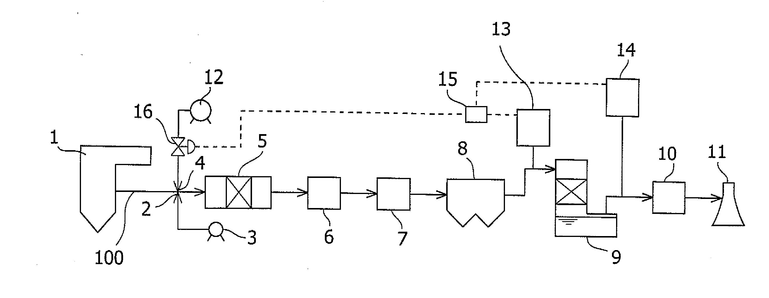
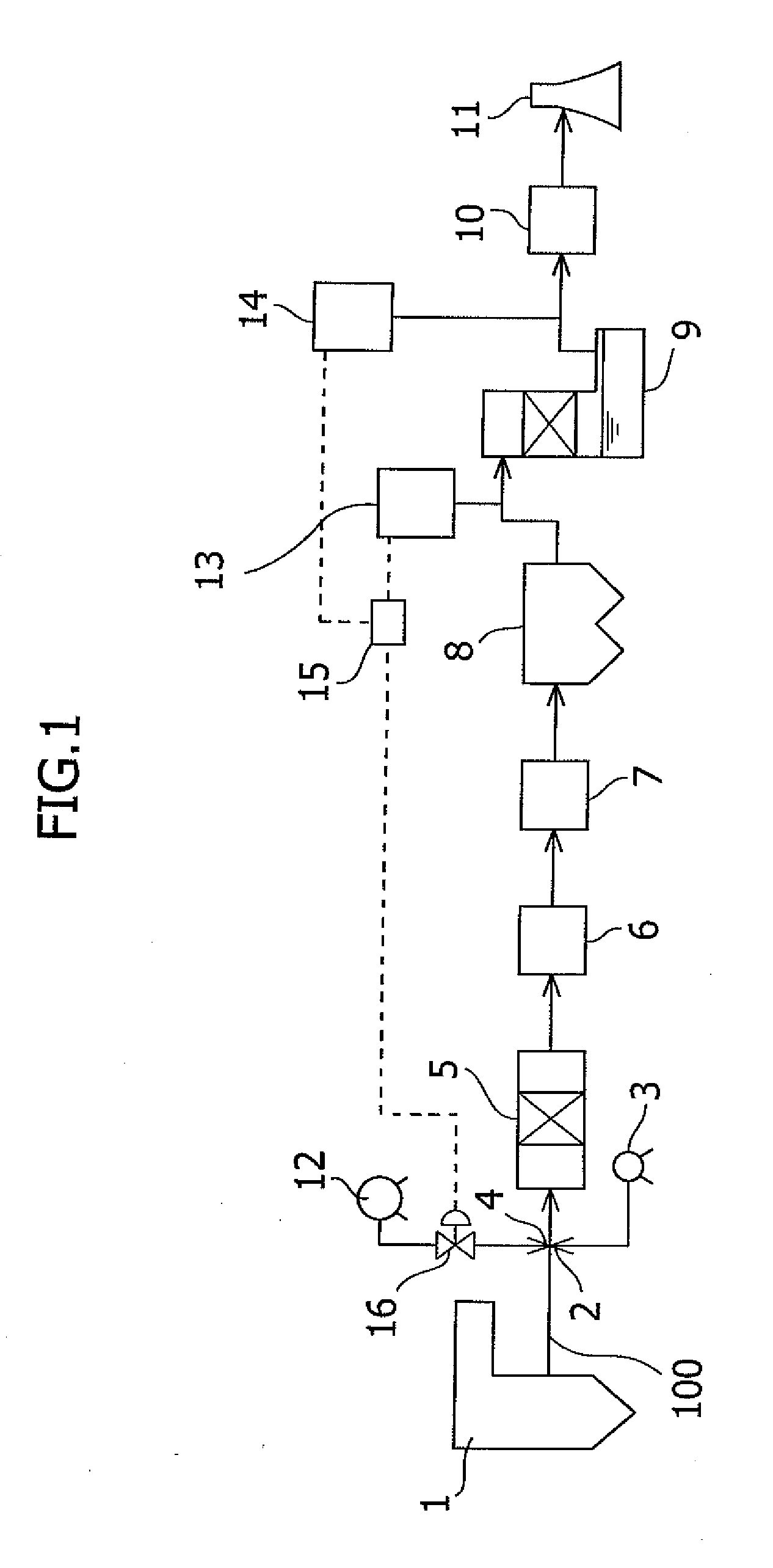
[0032] The entire image of the exhaust gas treatment system including the mercury removal system of the present invention will next be described based on FIG. 1.

[0033] An exhaust gas containing NOx, SOx and mercury discharged from a boiler passes through a reductive denitration unit 5 for reducing the NOx, an air heater 6, a heat recovery unit 7 and a dust collector 8, is treated through a desulfurization unit for removing the SOx and a reheater 10, and then is discharged from a chimney 11.

[0034] An NH3 injection site 2 is disposed upstream of the reductive denitration unit 5 and reduction of the NOx is performed by NH3 fed from an NH3 tank 3.

[0035] As illustrated in FIG. 1, the mercury removal system of the present invention may have, in addition to the above-described exhaust gas treatment system, a concentration measuring unit 13 of the gaseous agent for mercury chlorination disposed upstream of the desulfurization unit 9 in the flue; a calculation unit 15 for calculating an i...


PUM

PropertyMeasurementUnit
temperatureaaaaaaaaaa
concentrationaaaaaaaaaa
temperatureaaaaaaaaaa

Abstract

Provided is a system for removing mercury from a mercury-containing exhaust gas, which contains a mercury chlorinating agent feed unit for feeding a mercury chlorinating agent to an flue exhaust gas containing nitrogen oxide, sulfur oxide and mercury, a reductive denitration unit for reducing the nitrogen oxide, and a desulfurization unit for removing the sulfur oxide, characterized in that the mercury chlorinating agent feed unit further comprises a heating unit for heating a non-gaseous agent for mercury chlorination which is in the non-gaseous form under normal temperature and normal pressure or a gasifying unit for obtaining a gaseous agent for mercury chlorination from the non-gaseous agent for mercury chlorination. The present invention makes it possible to provide a mercury removal process and system which have high reliability and can be operated at a low cost.

Description

RELATED APPLICATION [0001] The present application is based on, and claims priority from, Japanese Application Number 2005-367344, filed Dec. 21, 2005, the disclosure of which is hereby incorporated by reference herein in its entirety. BACKGROUND OF THE INVENTION [0002] 1. Field of the Invention [0003] The present invention relates to a mercury removal system and mercury removal process for removing mercury contained in a gas discharged from combustion equipment. [0004] 2. Background Art [0005] Exhaust gases released when coal or heavy oil is burnt contain ash dust, SOx (sulfur oxides) and NOx (nitrogen oxides) and they sometimes contain metallic mercury. [0006] For treating this metallic mercury, a variety of processes or apparatuses have recently been devised, used in combination with a denitration apparatus for reducing NOx and a wet desulfurization apparatus using an alkaline absorbing solution as a SOx absorber. [0007] As a process for treating metallic mercury in an exhaust ga...

Claims


Application Information

Patent Timeline
Patent Type & Authority Applications(United States)
IPC IPC(8): B01D53/00B01D50/00B01D53/34B01D53/86
CPCY10S423/05B01D53/64Y02A50/20
Inventor HONJO, SHINTAROOKADA, KENICHIOKINO, SUSUMUTAKEUCHI, YASUHIROSUGITA, SATORUNAKAYAMA, YOSHIO
Owner MITSUBISHI POWER LTD
Why Eureka
Try Eureka