Method of manufacturing toner

a manufacturing method and technology of toner, applied in the field of toner manufacturing methods, can solve the problems of reduced toner diameter, extremely deteriorated powder flowability, and reduced toner diameter, and achieve the effect of easy granulation

Inactive Publication Date: 2007-08-30
SHARP KK
View PDF6 Cites 9 Cited by
  • Summary
  • Abstract
  • Description
  • Claims
  • Application Information

AI Technical Summary

Benefits of technology

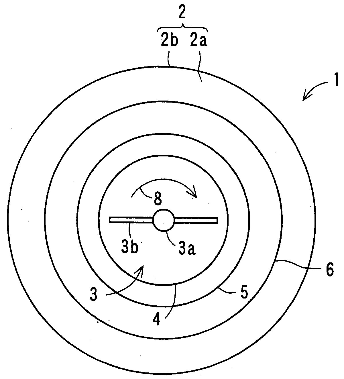
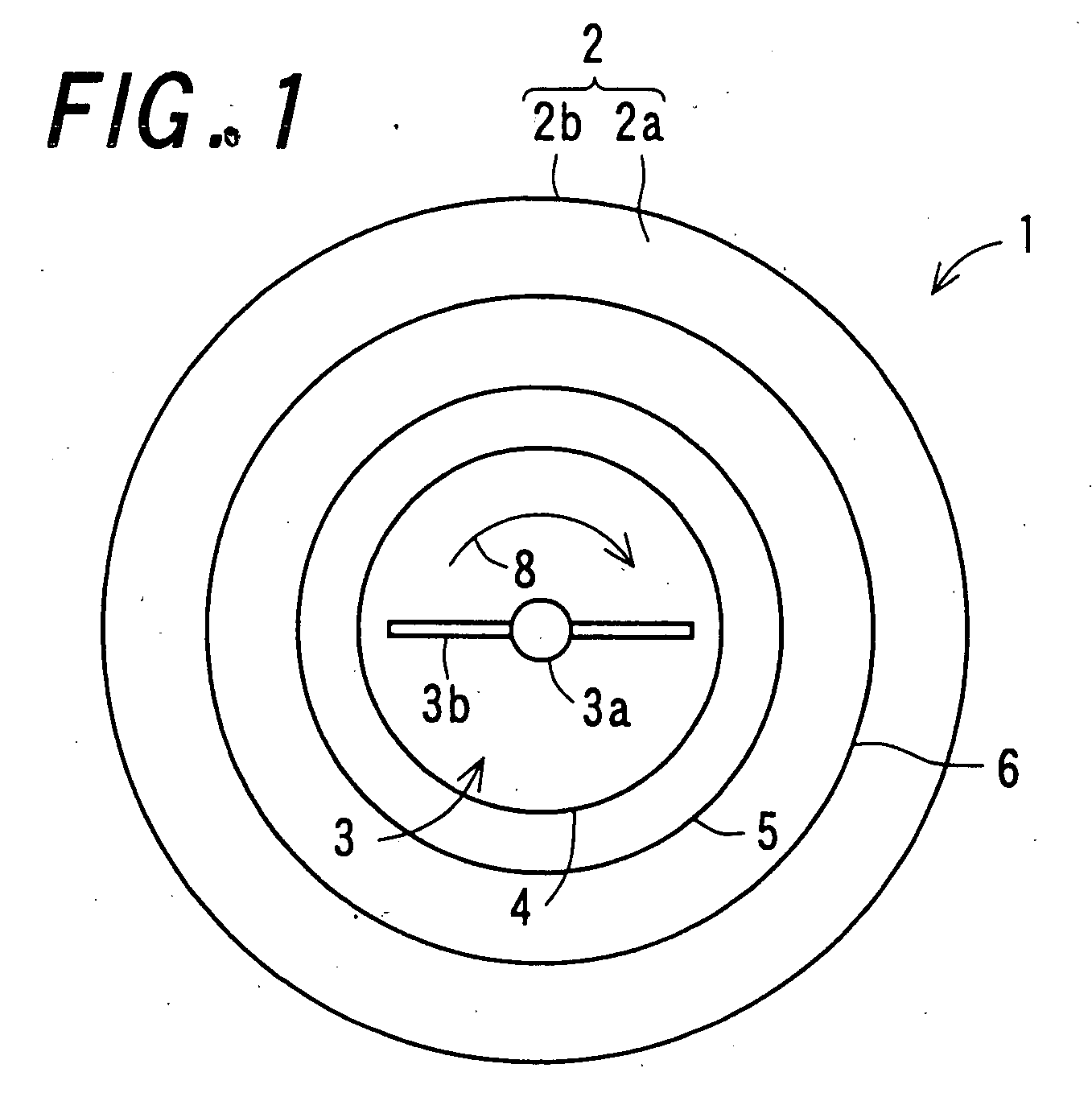
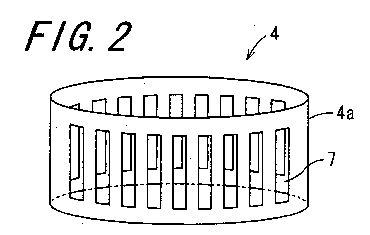
[0009]An object of the invention is to provide a method of manufacturing a toner, using a shearing force for granulation, in which bubbles are prevented from arising upon application of the shearing force, thus manufacturing a toner having a reduced approximately uniform particle diameter of around 5 μm and an approximately uniform shape.

Problems solved by technology

Regarding the enhancement in definition and resolution of the image, the reduction in diameter of toner particles is one of problems to be solved from the aspect of the developer.
The diameter-reduced toner manufactured by the pulverization method contains particles of which shapes are not uniform, and has an extremely deteriorated powder flowability.
When such a toner is used, the toner is unevenly charged before supplied to an electrostatic latent image, for example, which possibly generates unevenness in density or color of an image being formed.
The polymerization method has a drawback such that the binder resin is limited to vinylic polymers such as polyvinyl chloride, which can be manufactured by radical polymerization.
When the wet method is implemented in industrial scale, a large amount of waste liquid containing organic solvent is generated.
Considering environmental problems, the waste liquid should not be disposed without treatment.
Accordingly, there arises a need of establishing a large-scale disposing facility for collecting the organic solvent, resulting in a higher cost for manufacturing a toner as compared to the other methods.
In those techniques, however, the generation of bubbles cannot be sufficiently prevented, so that a part of the obtained toner is coarsened, resulting in uneven particle diameter and shape of the toner.
Thus, those techniques have a drawback that a diameter-reduce toner as desired cannot be obtained.

Method used


Image

  • Method of manufacturing toner
  • Method of manufacturing toner
  • Method of manufacturing toner

Examples


example 1

[0066][Kneaded Product Preparing Step]

[0067]There were provided 8 parts of carbon black particles acting as a colorant: NIPX 60 (trade name) manufactured by Degussa, Inc., 5 parts by weight of ester wax particles acting as a release agent: WEP-5 (trade name) manufactured by NOF Corporation, 90 parts of polyester acting as binder resin (having a softening temperature Tm of 125° C. and a glass transition temperature Tg of 58° C.) manufactured by Kao Corporation, and 2 parts of a charge control agent: TRH (trade name) manufactured by Hodogaya Chemical Co., Ltd. These constituent components were mixed by using a mixer: Henschel Mixer (trade name) manufactured by Mitsui Mining Co., Ltd. to obtain a raw material admixture. By using a twin-screw extruding and kneading machine: PCM-30 (trade name) manufactured by Ikegai Co., Ltd., the obtained raw material admixture was kneaded at a kneading temperature T1 of 140° C. obtained by (Tm+15° C.), which is higher than a softening temperature Tm o...


PUM

PropertyMeasurementUnit
pressureaaaaaaaaaa
temperatureaaaaaaaaaa
particle diameteraaaaaaaaaa

Abstract

There is provided a method of manufacturing a toner, using a shearing force for granulation, in which bubbles are prevented from arising upon application of the shearing force, thus manufacturing a diameter-reduced toner having a particle diameter of about 5 μm which is favorable for enhancement in definition and resolution of images. Upon granulating after a kneaded product of toner raw material is mixed with water dispersion, an interior part of granulating system is heated and pressurized and moreover, both of the shearing force and collision force are applied to the kneaded product of toner raw material by use of a high-speed rotating dispersion type granulator composed of a cylindrical pressure-resistant container, a spinning rotor, following screens, and a fixed screen.

Description

CROSS-REFERENCE TO RELATED APPLICATION[0001]This application claims priority to Japanese Patent Application No. JP 2006-53744, which was filed on Feb. 28, 2006, the contents of which, are incorporated herein by reference, in their entirety.BACKGROUND OF THE INVENTION[0002]1. Field of the Invention[0003]The present invention relates to a method of manufacturing a toner.[0004]2. Description of the Related Art[0005]An electrophotographic image forming apparatus comprises an image forming process mechanism including: a photoreceptor; a charging section for charging a photoreceptor surface; an exposing section for irradiating with signal light the photoreceptor surface being charged, to form thereon an electrostatic latent image corresponding to image information; a developing section for supplying a toner contained in a developer to the electrostatic latent image formed on the photoreceptor surface, to form thereon a toner image; a transfer section provided with a transfer roller for tr...

Claims


Application Information

Patent Timeline
Patent Type & Authority Applications(United States)
IPC IPC(8): G03G9/08
CPCG03G9/0808G03G9/081G03G9/0815G03G9/08764G03G9/08728G03G9/08753G03G9/08755G03G9/0817
Inventor MATSUMOTO, KATSURUSHIBAI, YASUHIROARIYOSHI, SATORU
Owner SHARP KK
Why Eureka
Try Eureka