Plasma-Polymerisation Of Polycylic Compounds

a technology of polycylic compounds and plasma, which is applied in the field of plasma-polymerisation of polycylic compounds, can solve the problems of difficult to solve conjugated polymer systems, limited choice of conjugated polymer systems for given applications, and limited application range,

Inactive Publication Date: 2007-08-30
DANMARKS TEKNISKE UNIV
View PDF2 Cites 37 Cited by
  • Summary
  • Abstract
  • Description
  • Claims
  • Application Information

AI Technical Summary

Benefits of technology

[0014] (b) reacting said pendant heteroaromatic rings or ring systems with one or more second heteroaromatic compounds so as to form a layer of an electrically conducting material including the pendant heteroaromatic rings or ring systems and the second heteroaromatic compounds.
[0015] A fifth aspect of the present invention relates to an object comprising a substrate, wherein at least a part of the surface of said substrate is coated with a layer of a polymeric material and, integrated therewith, an electrically conducting material, said polymeric material being covalently bonded to the substrate and having pendant heteroaromatic rings or ring systems, and said electrically conducting material being the reacting product of the pendant heteroaromatic rings or ring systems of the polymeric material and one or more second heteroaromatic compounds.

Problems solved by technology

Conjugated polymer systems are, however, generally difficult to get into solution.
The choice of a conjugated polymer system for a given application may thus be restricted by the possibilities for finding a suitable compromise between functionality and processability.
On conducting substrates, this can be achieved by electrochemical polymerisation, but this method is rarely suited for large-scale applications.
Independent of the polymerisation route adhesion or bonding to the substrate has always caused problems due to the large difference in surface energy between the conjugated polymers and almost any substrate chosen.

Method used


Image

  • Plasma-Polymerisation Of Polycylic Compounds
  • Plasma-Polymerisation Of Polycylic Compounds
  • Plasma-Polymerisation Of Polycylic Compounds

Examples


example 1

lymerisation of 1,3-benzodioxole and 1,4-benzodioxane

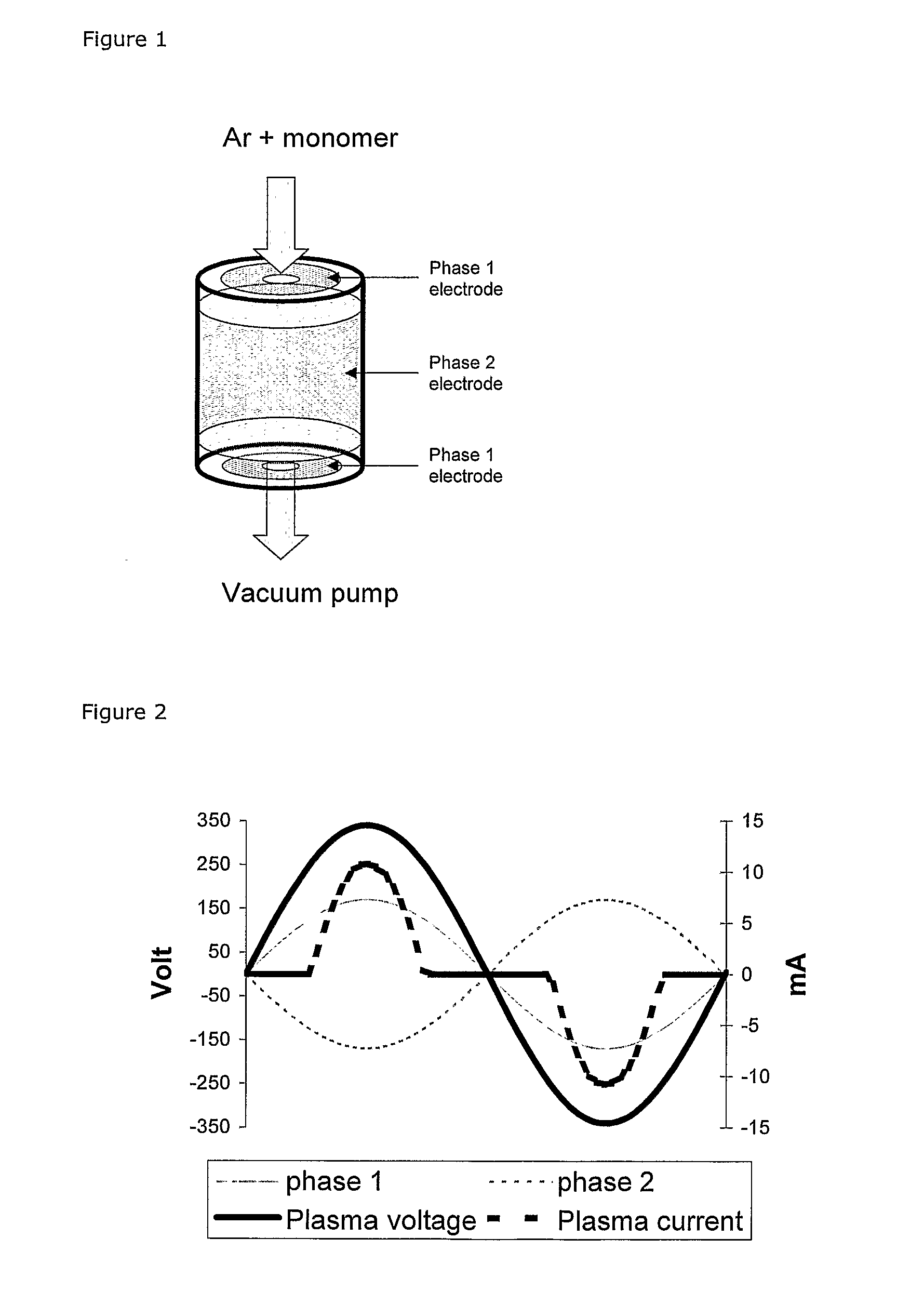
[0144] 1,4-Benzodioxane and 1,3-benzodioxole were plasma polymerised in the described low-power plasma system.

[0145] An argon flow of 5 sccm was used in all experiments. The plasma power was selected between 0.5 and 0.85 W / L and the partial pressure of monomer was 3.7 Pa for 1,4-benzodioxan and 4.2 Pa for 1,3-benzodioxole (without plasma).

[0146] For both monomers ΔPplasma were negative (−1 Pa and −1.6 Pa respectively) regardless of the plasma power.

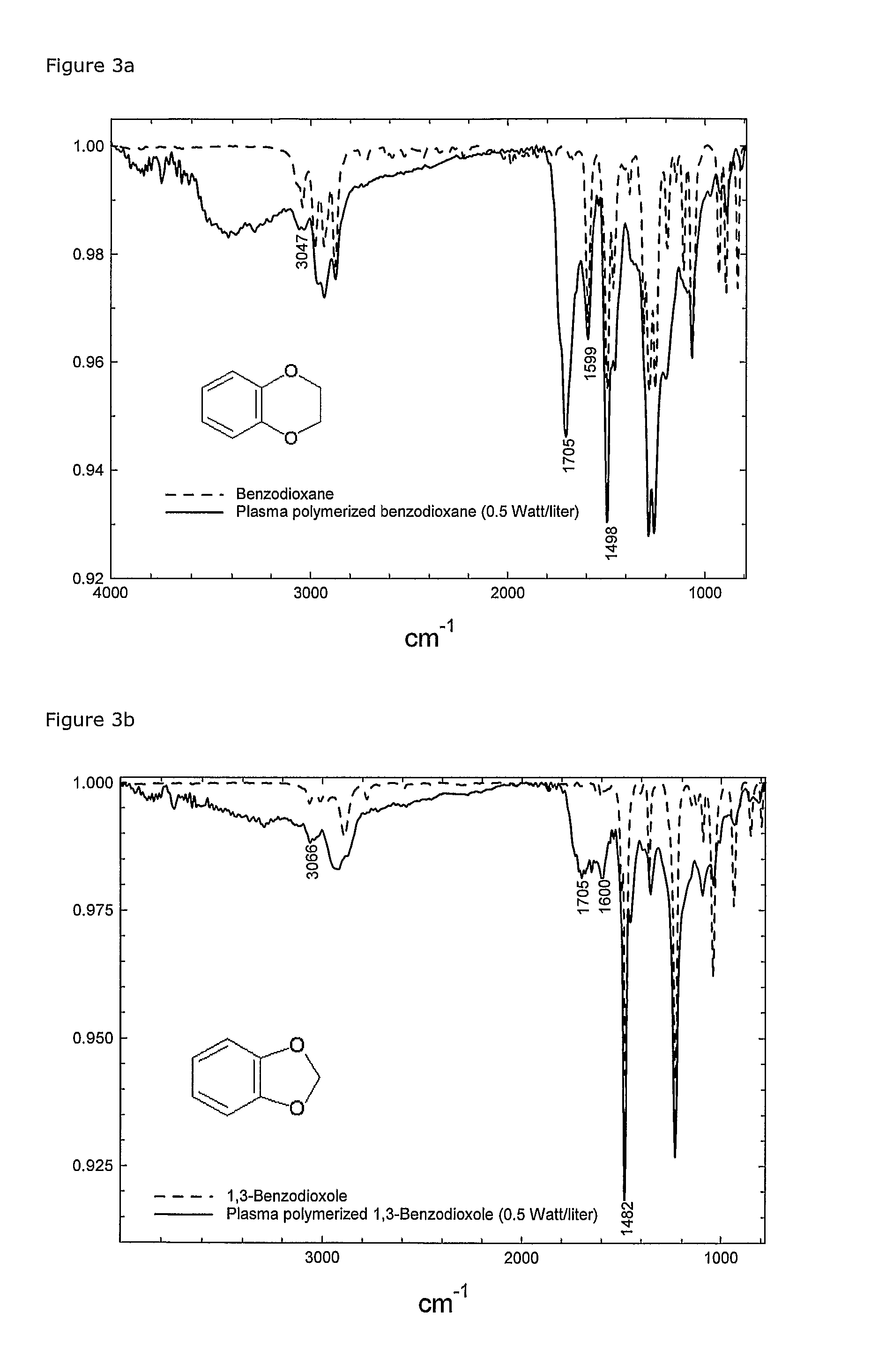
[0147]FIGS. 3a and 3b show FTIR spectra of the monomers and the plasma polymerised films.

[0148] In both cases, a preservation of the benzene ring (C═C bonds at ˜1490 cm−1 and 1600 cm−1 and ═C—H bonds ˜3045-3065 cm−1) and appearance of carbonyl groups (C═O ˜1705 cm−1) was observed. The carbonyl group can only have origin in the oxygen in the dioxane / dioxole rings and must be one of the resulting products of the polymerisation mechanism.

[0149] The negative ΔPplasma indicates that the...

example 2

lymerisation of 3,4-ethylenedioxythiophene Followed by Oxidative Polymerisation of poly-(3,4-ethylenedioxythiophene)

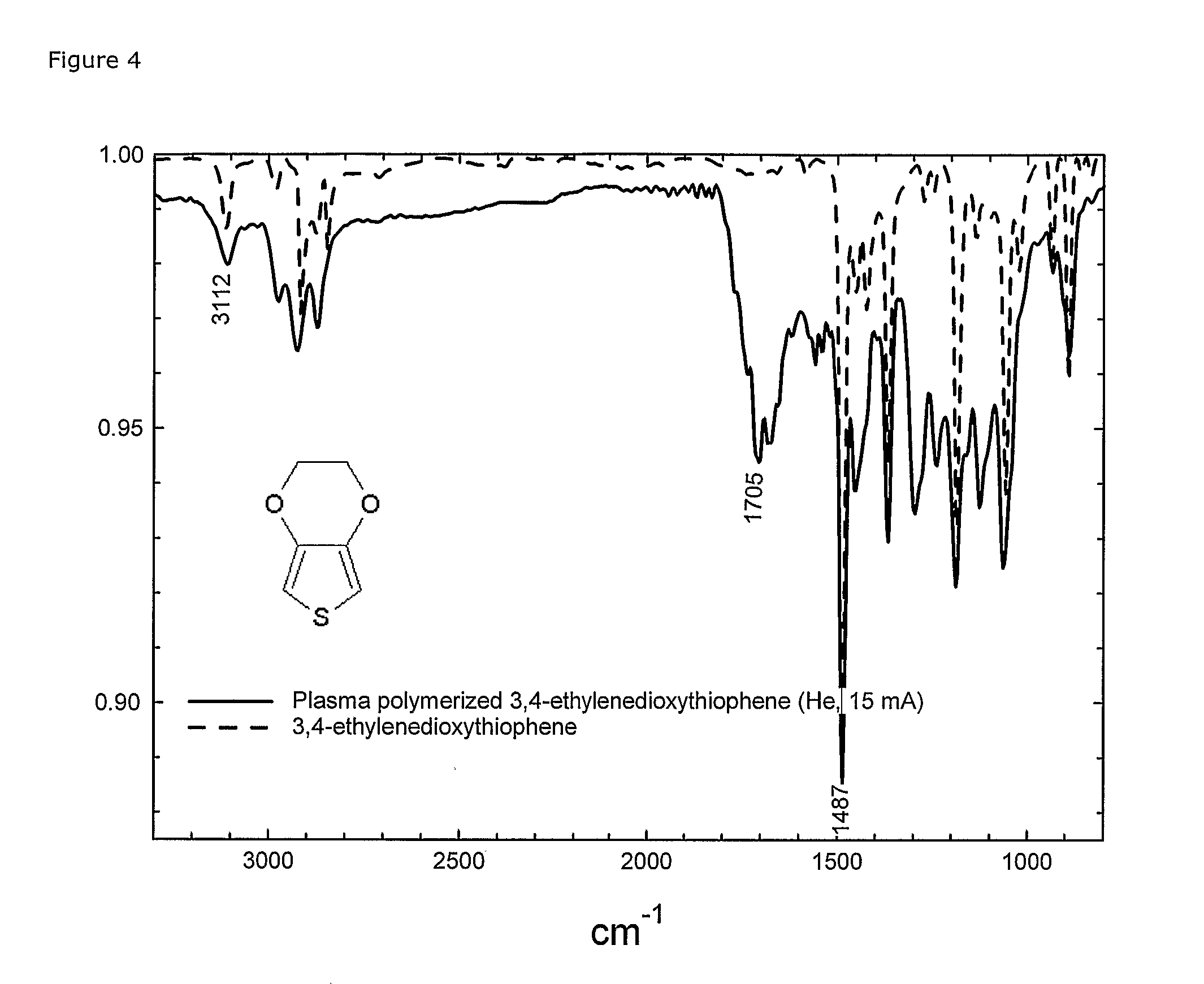
[0151] 3,4-ethylenedioxythiophene (EDT) was plasma polymerised in the described low-power plasma system on polyethylene and PET foils as well as on glass slides. A large range of parameter settings has been tried (results not included). Under mild plasma conditions (e.g. power less than 0.5 W / L, He as preferred carrier-gas and total pressure 25 Pa) the plasma polymerised film (FTIR spectra, FIG. 4) showed significant signs that the thiophene ring structure was preserved, whereas the dioxane-ring was used for the polymerisation, leaving among others carbonyl groups as product.

[0152] The peak at 1705 shows the formed carbonyl group. The C═C bond in the thiophene-ring was seen both in the monomer and the plasma polymerised film at 1487 cm−1. Of really great importance is the —C—H peak at 3112 cm−1 showing that the α-H on the thiophene ring was preserved in the film. The ...

example 3

lymerisation of 3,4-ethylenedioxythiophene as a Route to Micro-Patterning of Conducting poly-(3,4-ethylenedioxythiophene) Films by Lift-Off Technique

[0155] A silicium wafer was coated with photo resist and patterned by ordinary lithographic technique (FIG. 5), cf. R. Glang, Generation of patterns in thin films, in: Handbook of thin-film Technology, McGraw-Hill, New York, 1970, pp 7-10.

[0156] The wafer was then plasma coated with EDT in an equivalent way as described in Example 2, but with argon as carrier gas (argon flow 5 sccm, power 0.5 W / L, pressure 9.5 Pa, polymerisation time 90 sec.). Due to the harsh chemical conditions under the lift-off procedure, it was an advantage to pre-treat the wafer with H2 plasma (according to patent EP 01931463.2)

[0157] After the plasma polymerisation, a mixture of EDT monomer and iron(III)tosylate in a 20% ethanol solution was spin coated on the wafer and polymerised (according to Example 2). The residual from the oxidative polymerisation (Fe(II)...


PUM

PropertyMeasurementUnit
thicknessaaaaaaaaaa
partial pressureaaaaaaaaaa
pressureaaaaaaaaaa

Abstract

The present invention relates to a method for the preparation of a layer of a plasma-polymerised material on the surface of a substrate, e.g. a substrate of a glass, an organosiloxane-based or polysiloxane-based material, silicon, fluoro-polymer (e.g. Teflon®), etc. The present invention also relates to novel objects and microstructured or micro-patterned devices, e.g. by lift-off techniques, in particular such objects and devices that have layers of electrically conducting materials providing a conductivity of at least 0.01 S/cm. A feature of the invention is the plasma-polymerization of a compound including at least one polycyclic compound, said polycyclic compound(s) comprising a non-aromatic heterocyclic ring fused to an aromatic or heteroaromatic ring or ring system. Examples of such compounds are 3,4-ethylenedioxythiophene (EDT) forming layers of poly(ethylenedioxythiophene) (PEDT), and piperonylamine, piperonyloyl chloride, safrole, 3,4-ethylenedioxypyrrole, 3,4-ethylenedioxy-N-methylpyrrole, and 3,4-methylenedioxythiophene.

Description

FIELD OF THE INVENTION [0001] The present invention relates to a method for the preparation of a layer of a plasma-polymerised material on the surface of a substrate. The present invention also relates to novel objects and microstructured devices, in particular such objects and devices that have layers of electrically conducting materials. BACKGROUND OF THE INVENTION [0002] Preparation of Electrically Conducting Surfaces Relies on the Ability to Deposit these Materials as thin, even coatings. A number of routes are available for this purpose, depending on the polymer and substrates in question. Most common are solution processing in the form of spin coating, solvent casting or printing. Conjugated polymer systems are, however, generally difficult to get into solution. It is often necessary to derivatise the polymer with soluble side chains or to dope the polymer with polyelectrolytes acting as solubilisers in order to be able to process these polymers. The choice of a conjugated pol...

Claims


Application Information

Patent Timeline
Patent Type & Authority Applications(United States)
IPC IPC(8): H01L21/00B32B9/04B05D7/24
CPCB05D1/62Y10T428/265H01L51/0037H01L51/0016Y10T428/31855Y10T428/31504H10K71/221H10K85/1135
Inventor WINTER-JENSEN, BJOMWEST, KELD
Owner DANMARKS TEKNISKE UNIV
Why Eureka
Try Eureka