Polishing apparatus and polishing method

a technology of polishing apparatus and polishing rate, which is applied in the direction of manufacturing tools, machining electric circuits, and abrasive surface conditioning devices. it can solve problems such as delay of signal, difficulty in uniform supply of chemical liquid (slurry) to an entire surface of the wafer, and problematic increase of electric capacity between adjacent interconnections. it achieves uniform supply of chemical liquid and uniform polishing ra

Inactive Publication Date: 2007-09-06
KODERA MASAKO +7
View PDF16 Cites 21 Cited by
  • Summary
  • Abstract
  • Description
  • Claims
  • Application Information

AI Technical Summary

Benefits of technology

[0014] The present invention has been made in view of the aforementioned drawbacks which would be caused when a material having a low permittivity is used. It is, therefore, a first object of the present invention to provid

Problems solved by technology

However, when a wafer is polished with a low process pressure, it is difficult to supply a chemical liquid (slurry) uniformly to an entire surface of the wafer and maintain a uniform polishing rate within the surface of the wafer at the same time.
However, when intervals between metal interconnections become smaller, electric capacity between adjacent interconnections is problematically increased.
Thus, an increased electric capacity between interconnections may cause delay of signal so as to inhibit an operation speed of an integrated circuit from being improved.
With conventional insulating materials, it is difficult to provide both of sufficiently low permittivity and insulation characteristics.
In a damascene process, when a material having a low permittiv

Method used


Image

  • Polishing apparatus and polishing method
  • Polishing apparatus and polishing method
  • Polishing apparatus and polishing method

Examples


first embodiment

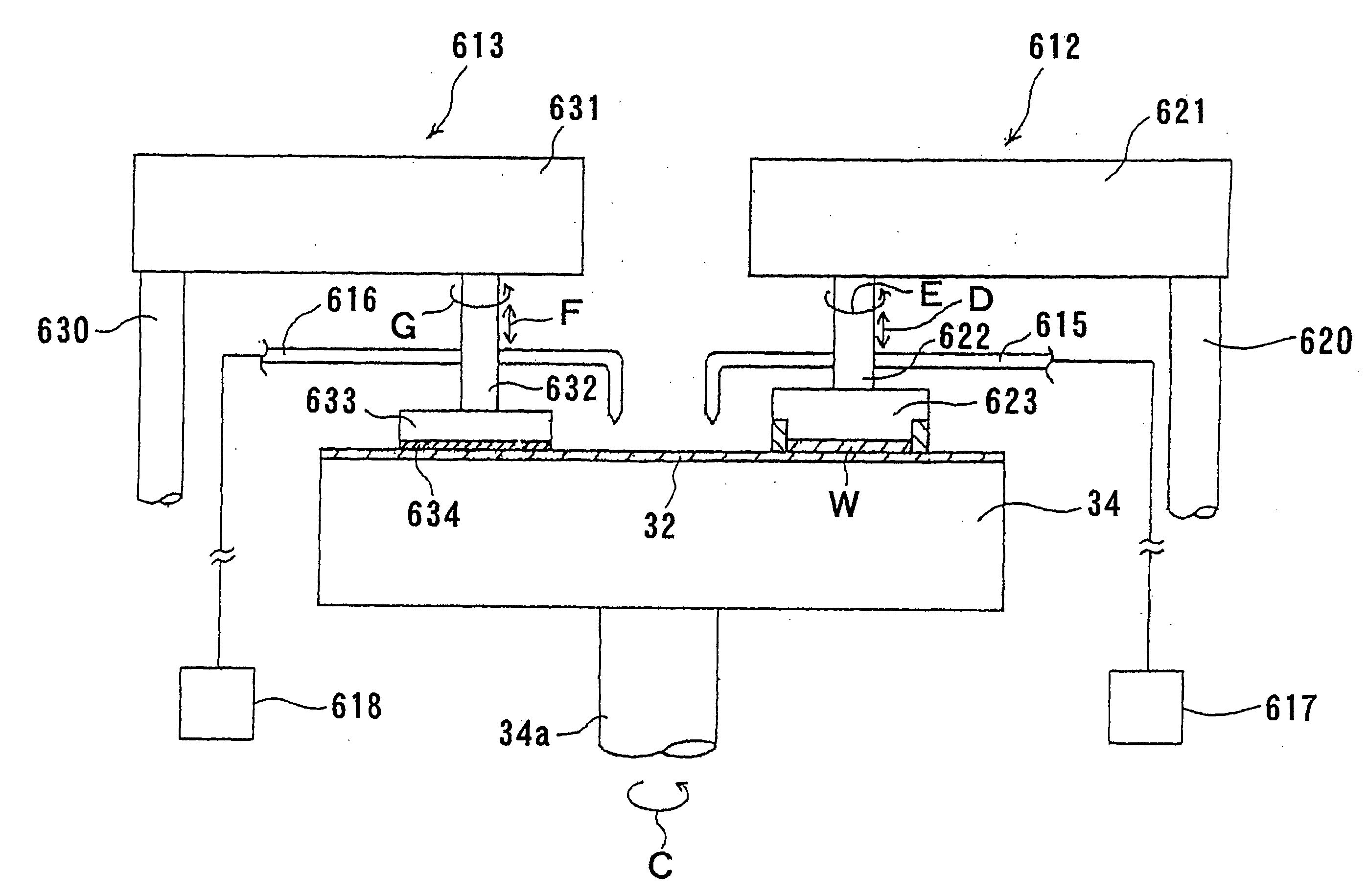
[0143]FIG. 10 is a schematic view showing a polishing apparatus 30 according to the present invention. As shown in FIG. 10, the polishing apparatus 30 includes a polishing table 34 having a polishing surface 32 attached on an upper surface thereof, a top ring 36 for holding a workpiece such as a semiconductor wafer W on a lower surface thereof, a top ring head 40 pivotable about a pivot shaft 38, a chemical liquid supply nozzle 42 which serves as a chemical liquid supply mechanism for supplying a chemical liquid (polishing liquid) onto the polishing surface 32, and a controller 44 for controlling operation of the polishing apparatus 30. The polishing surface 32 on the polishing table 34 is formed by polyurethane foam, a fixed abrasive, or an impregnated abrasive.

[0144] The polishing table 34 is coupled to a motor 46 located below the polishing table 34 and rotated by the motor 46. Thus, the motor 46 serves as a rotation mechanism to rotate the polishing table 34 and the polishing su...

second embodiment

[0205]FIG. 18 is a schematic view showing a polishing apparatus 300 according to the present invention. The polishing apparatus 300 perform a composite electrolytic polishing process. The polishing apparatus 300 has a cylindrical electrolytic cell 302 having a bottom and a top ring 304 disposed above the electrolytic cell 302. The electrolytic cell 302 has an opening at an upper portion thereof and holds an electrolytic solution 301 therein. The top ring 304 detachably holds a semiconductor wafer W in a state such that the semiconductor wafer W faces downward. The electrolytic solution 301 may comprise a chemical liquid including an oxidizer, a chelating agent, and abrasive particles.

[0206] The electrolytic cell 302 is coupled directly to the main shaft 306, which is rotated by a rotation mechanism such as a motor. A cathode plate (electrode) 308 is disposed horizontally at a lower portion of the electrolytic cell 302 and immersed in the electrolytic solution 301. The cathode plate ...

third embodiment

[0220]FIG. 19 is a schematic view showing a polishing apparatus 430 according to the present invention. As shown in FIG. 19, the polishing apparatus 430 includes a polishing table 34 having a polishing surface 32 attached on an upper surface thereof, a top ring 36 for holding a workpiece such as a semiconductor wafer W on a lower surface thereof, a top ring head 40 pivotable about a pivot shaft 38, a chemical liquid supply nozzle 42 which serves as a chemical liquid supply mechanism for supplying a chemical liquid (polishing liquid) onto the polishing surface 32, and a controller 44 for controlling operation of the polishing apparatus 30. The polishing surface 32 on the polishing table 34 is generally formed by resin of polyurethane foam, a fixed abrasive, or an impregnated abrasive.

[0221] The polishing table 34 is coupled to a motor 46 located below the polishing table 34 and rotated by the motor 46. Thus, the motor 46 serves as a rotation mechanism to rotate the polishing table 34...


PUM

PropertyMeasurementUnit
Pressureaaaaaaaaaa
Angleaaaaaaaaaa
Speedaaaaaaaaaa

Abstract

A polishing apparatus (30) has a polishing surface (32), a top ring (36) for holding a wafer (W), motors (46, 56) to move the polishing surface (32) and the wafer (W) relative to each other at a relative speed, and a vertical movement mechanism (54) to press the wafer (W) against the polishing surface (32) under a pressing pressure. The polishing apparatus (30) also has a controller (44) to adjust a polishing condition in a non-Preston range in which a polishing rate is not proportional to a product of the pressing pressure and the relative speed. The polishing apparatus (30) can simultaneously achieve uniform supply of a chemical liquid to a surface of the wafer (W) and a uniform polishing rate within the surface of the wafer (W).

Description

[0001] This application is a divisional application of Ser. No. 11 / 661,141, which is a National Stage Application of International Application Serial No. PCT / JP2005 / 016063, filed Aug. 26, 2005.TECHNICAL FIELD [0002] The present invention relates to a polishing apparatus and a polishing method, and more particularly to a polishing apparatus and a polishing method for polishing and planarizing a substrate such as a semiconductor wafer having an insulating film such as a low-k film and metal interconnections such as copper interconnections embedded in the insulating film. BACKGROUND ART [0003] From the viewpoints of easy processing and productivity, aluminum or aluminum alloy is generally employed as an interconnection material for forming interconnection circuits on a semiconductor substrate. As semiconductor devices have been required in recent years to have finer interconnections capable of processing at a higher speed, there has been a significant trend that copper is employed as a...

Claims


Application Information

Patent Timeline
IPC IPC(8): B23H3/00
CPCB23H5/08B24B53/001B24B53/017C09G1/02C25F3/02H01L21/7684H01L21/3212H01L21/32125H01L21/76814H01L21/76825C25F7/00
Inventor KODERA, MASAKOMOCHIZUKI, YOSHIHIROFUKUDA, AKIRAKODERA, AKIRAHIYAMA, HIROKUNITSUJIMURA, MANABUHIROKAWA, KAZUTOFUKUNAGA, AKIRA
Owner KODERA MASAKO
Why Eureka
Try Eureka