Localization of a Radioactive Source Within a Body of a Subject

Inactive Publication Date: 2007-09-06
NAVOTEK MEDICAL
View PDF92 Cites 39 Cited by
  • Summary
  • Abstract
  • Description
  • Claims
  • Application Information

AI Technical Summary

Benefits of technology

[0021] An aspect of some embodiments of the invention relates to use of an ionizing radiation source with an activity of 0.1 mCi or less as a target for non imaging localization or tracking, optionally in a medical context. The source of ionizing radiation is selected to reduce a biological effect on the patient and/or medical per

Problems solved by technology

Those techniques which employ ionizing radiation, such as fluoroscopy and CT, require sufficient amount

Method used


Image

  • Localization of a Radioactive Source Within a Body of a Subject
  • Localization of a Radioactive Source Within a Body of a Subject
  • Localization of a Radioactive Source Within a Body of a Subject

Examples


Example

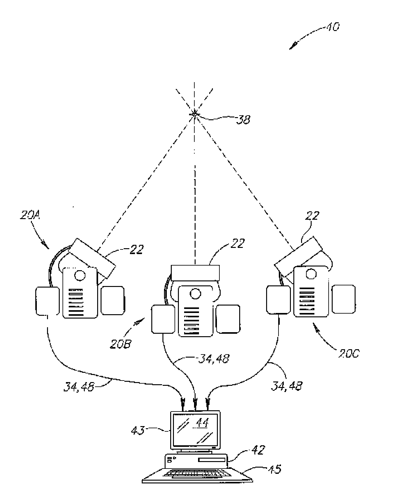
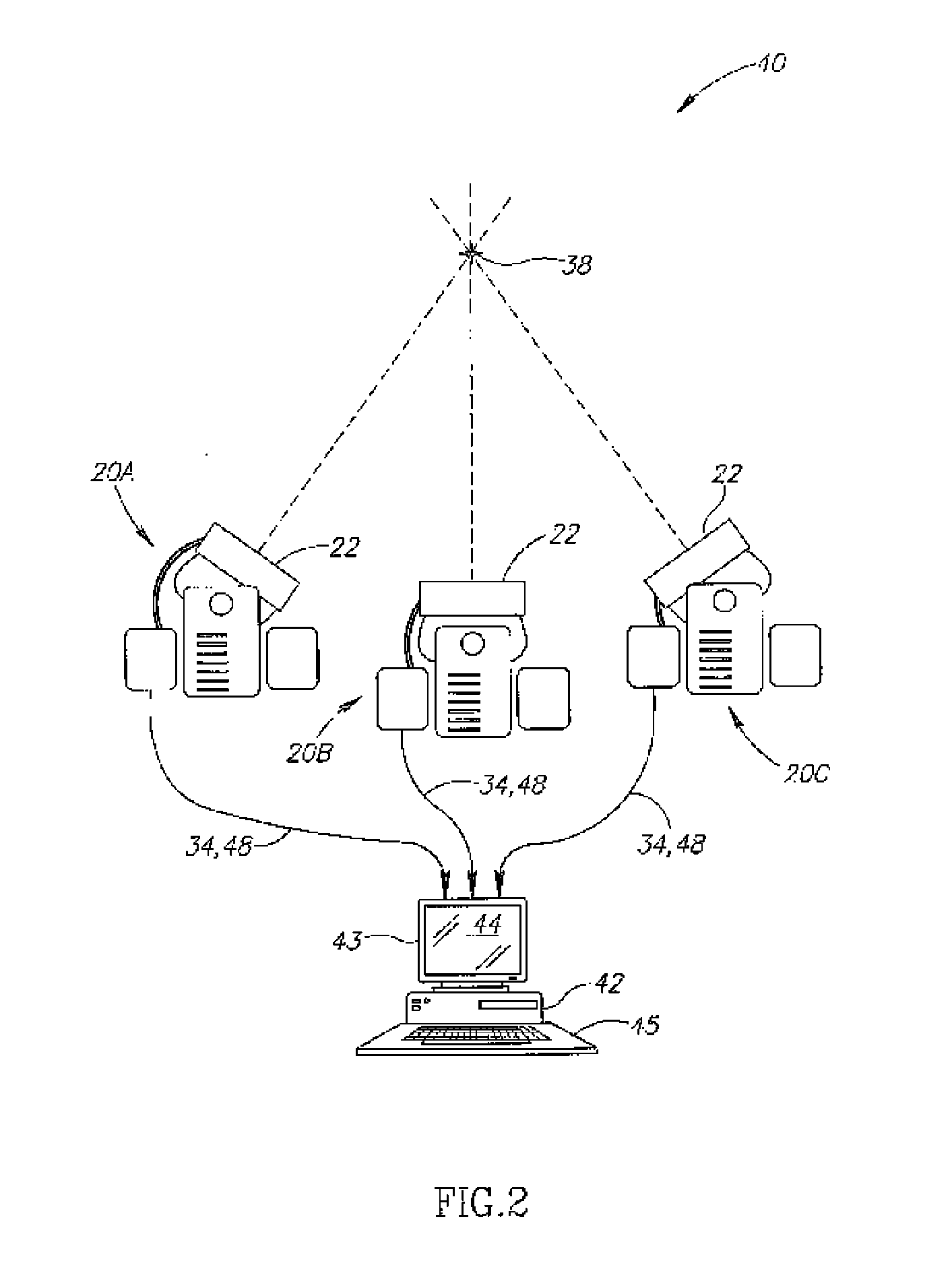
[0083] According to one embodiment of the invention (FIGS. 2 and 4), a computerized system 40 locates and / or tracks a device. In the embodiment depicted in FIG. 4, the device is a medical device. Medical devices include, but are not limited to, tools, implants, navigational instruments and ducts. Tools include, but are not limited to, catheters, canulae, trocar, cutting implements, grasping implements and positioning implements. Implants include, but are not limited to, brachytherapy seeds, stents and sustained release medication packets. Navigational instruments include, but are not limited to, guidewires. Ducts include, but are not limited to, tubing (e.g. esophageal tubes and tracheal tubes). In exemplary embodiments of the invention, one or more moving tools are tracked.

[0084] In an exemplary embodiment of the invention, position of the source is determined by non-imaging data acquisition. For purposes of this specification and the accompanying claims, the phrase “non-imaging” ...


PUM


Abstract

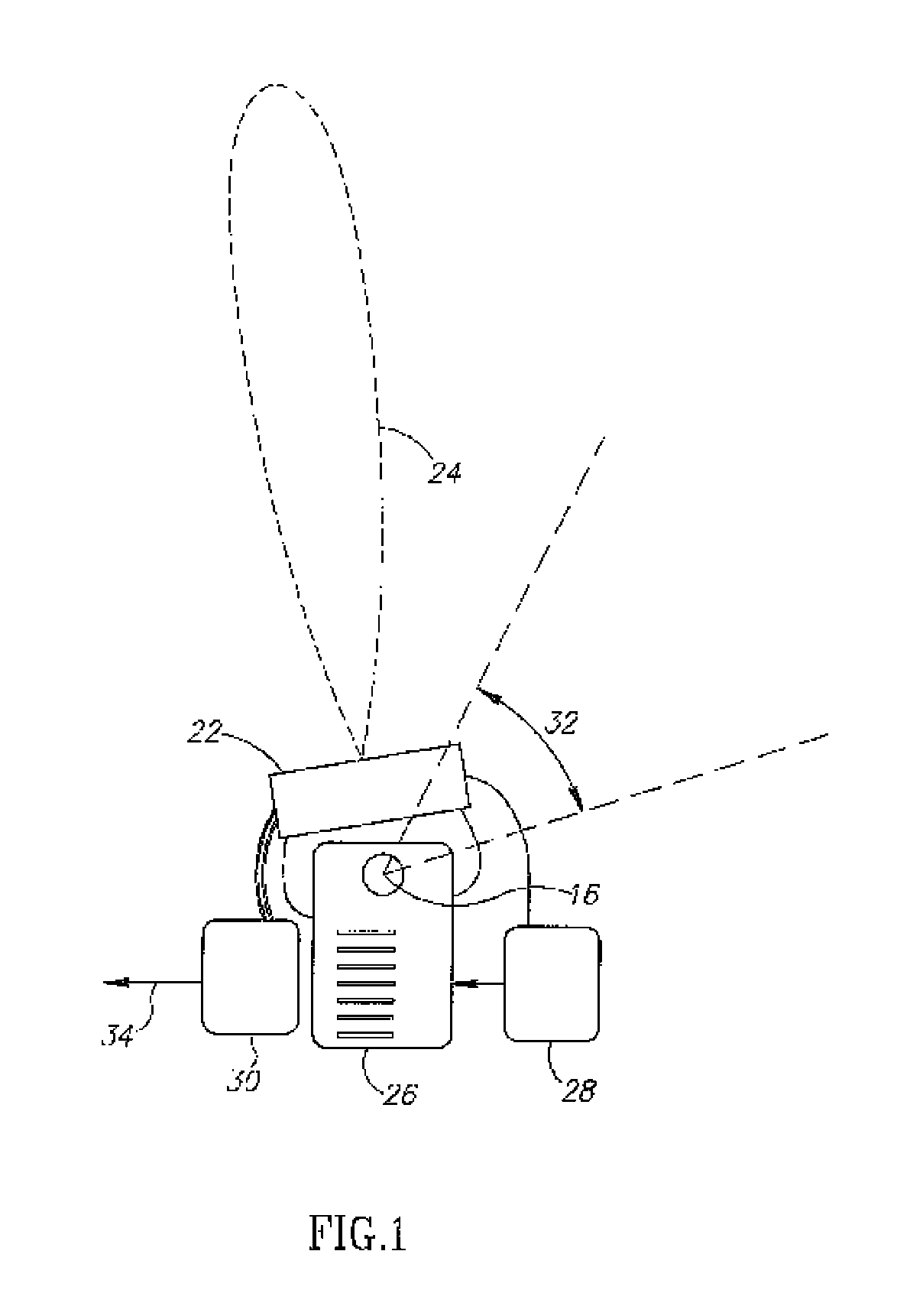
A computerized system 40 for locating a device. System 40 includes a sensor module 20 and a CPU 42. A radioactive source 38, associated with the device, produces a signal in the form of radioactive disintegrations. Module 20 includes a radiation detector 22 capable of receiving a signal from source 38 attached to the device. Module 20 produces an output signal 34. CPU 42 receives output signal(s) 34 and translates output 34 into directional information relating to a position of source 38.

Description

RELATED APPLICATIONS [0001] The present application claims the benefit under 35 USC 119(e) of U.S. Provisional Application No. 60 / 600,725 filed on Aug. 12, 2004; entitled “Medical Navigation System Base on Differential Sensor”; 60 / 619,792 filed on Oct. 19, 2004, entitled “Using a Catheter or Guidewire Tracking System . . . :”, and 60 / 619,897 filed on Oct. 19, 2004, entitled “Using a Radioactive Source as the Tracked . . . :”, the disclosures of which are incorporated herein by reference.FIELD OF THE INVENTION [0002] The present invention relates to location and tracking of a source of ionizing radiation, for example within a body of a subject. BACKGROUND OF THE INVENTION [0003] Existing techniques for intrabody tracking include direct video imaging using a laparoscope; fluoroscopy (performance of the procedure under continuous or periodic X-Ray imaging); electromagnetic tracking, optical tracking, computerized tomography (CT) tracking and ultrasonic image assisted tracking. Some of ...

Claims


Application Information

Patent Timeline
IPC IPC(8): G01T1/00A61N5/00
CPCA61B19/52A61B19/5244A61B6/4258A61B2019/5251A61B2019/542A61B2019/505A61B90/36A61B34/20A61B2034/105A61B2034/2051A61B2090/392
Inventor KORNBLAU, GIORABEN-ARI, SHLOMI
Owner NAVOTEK MEDICAL
Why Eureka
Try Eureka