
Propulsion motor

a technology of propulsion motor and propeller, which is applied in the direction of electrical equipment, nuclear energy generation, nuclear reactors, etc., to achieve the effects of good safety margin, greater energy, and greater explosion

Inactive Publication Date: 2007-09-06
CONCEICAO JOSE
View PDF1 Cites 2 Cited by
  • Summary
  • Abstract
  • Description
  • Claims
  • Application Information

AI Technical Summary

Benefits of technology

[0019] For fast ignition systems with materials from before patent applications the compression laser mass and the fast ignition laser mass is high join exhaust vessel mass. A innovation in this way is eliminate the massive compression laser system and substitute by super high explosive (SHE) compression or nanostructured chemical high explosive, that explosive lenses system can be triggered by less massive lasers, using for U / Pu compression (best nanostructured high explosive produce 10 kJ / g, using 100 g produce 1 MJ of energy—in ICF search the compression laser has 10 kJ) and after in the inner DT shell hit by fast ignition laser with explosions in the contention vessel, and the before target direct in the exhaust vessel, but the specific impulse is less, only for interplanetary travel, being this a system of intermediary mass by fuel trigger beam, with material from present invention applied to motor and processes.
[0022] The compression laser system can be very light, since the laser energy is in the mJ, or mW to MW of power, 10 ton of mass made of nanostructured materials according explosive used, for after trigger the chemical high explosive in the constitution of nuclear target, direct in the exhaust vessel, like in table 2, remaining between 50 / 120 ton of mass, removing some layers (50 ton case) with advanced fuel, and using an exhaust vessel of (4 m×4 m) from 17 ton of mass supporting 0.5 ton TNT equivalent impelling 500 ton of mass with a good security margin, without need reactions vessels, therefore in this case is adding 5 ton of mass according table 1, remaining 40 / 0.50 ton of mass, pending on first wall material nt-C (carbon nanotubes or buckytubes), to be smaller dense of all, comparable with ns-C (nanostructured carbon), that is a novelty and advantage.
[0030] Carbon nanotubes and copper, with thermal conductivity of 1300 W / mK, ideal for cylindrical tube that will transport the work fluid, like in the heat exchange. Carbon nanostructured can allow super capacitors with greater storage energy capacity from carbon films or carbon aerogel and due to high specific area around 800 m2 / g and high electrical conductivity, i.e., a large number of charge in a large surface (½ qV) and many of this capacitors can be linked in parallel adequate for high flux compression generator system or z-pinch systems to obtain little nuclear explosions with the intent to laser formation. In the vessel of contention or reactor made from carbon nanostructured from nanotubes, nanofiber, nanocomposites, etc., with density above 0.3 g / cm3 and 10 cm thickness a cylinder (2 m×2 m) remaining 800 kg of mass to retain explosions 0.002 ton TNT equivalent, around 15 MJ of energetic x-rays to made the laser, that is a novelty referenced to provisional patent application Ser. No. 10 / 528,225 and continuation-in-part Ser. No. 11 / 324,544 from before application or still a vessel of (3 m×3 m) remaining 1.8 ton of mass and supporting until 0.01 ton TNT equivalent around 80 MJ of energy to made the laser. Is possible nanostructured material of mix density linking the nano carbon to nano composite forming bulk nanostructured materials and the mass changing with density and thickness, being still lighter.

Problems solved by technology

To welding systems in bulk materials by agitation and friction and high strength fissure resistant, that is a crucial problem in this technology, metal lamina or ceramics like a shield or coating, nuclear explosive containment, structural motor component, like associate spaceship structures which benefits from mechanical, electrical, thermal and optical properties associate with carbon nanotubes, carbon nano fiber or nanostructured bulk metals obtained by SPD, fused carbon nanotubes, nanotubes from carbon aerogel, laser ablation, CVD, sol-gel, or any other method to obtain nano materials, nano crystals, nano grains, nano particles, applied or not, to bulk materials that constitute the motor and processes.

Method used


Image

  • Propulsion motor
  • Propulsion motor
  • Propulsion motor

Examples


Embodiment Construction

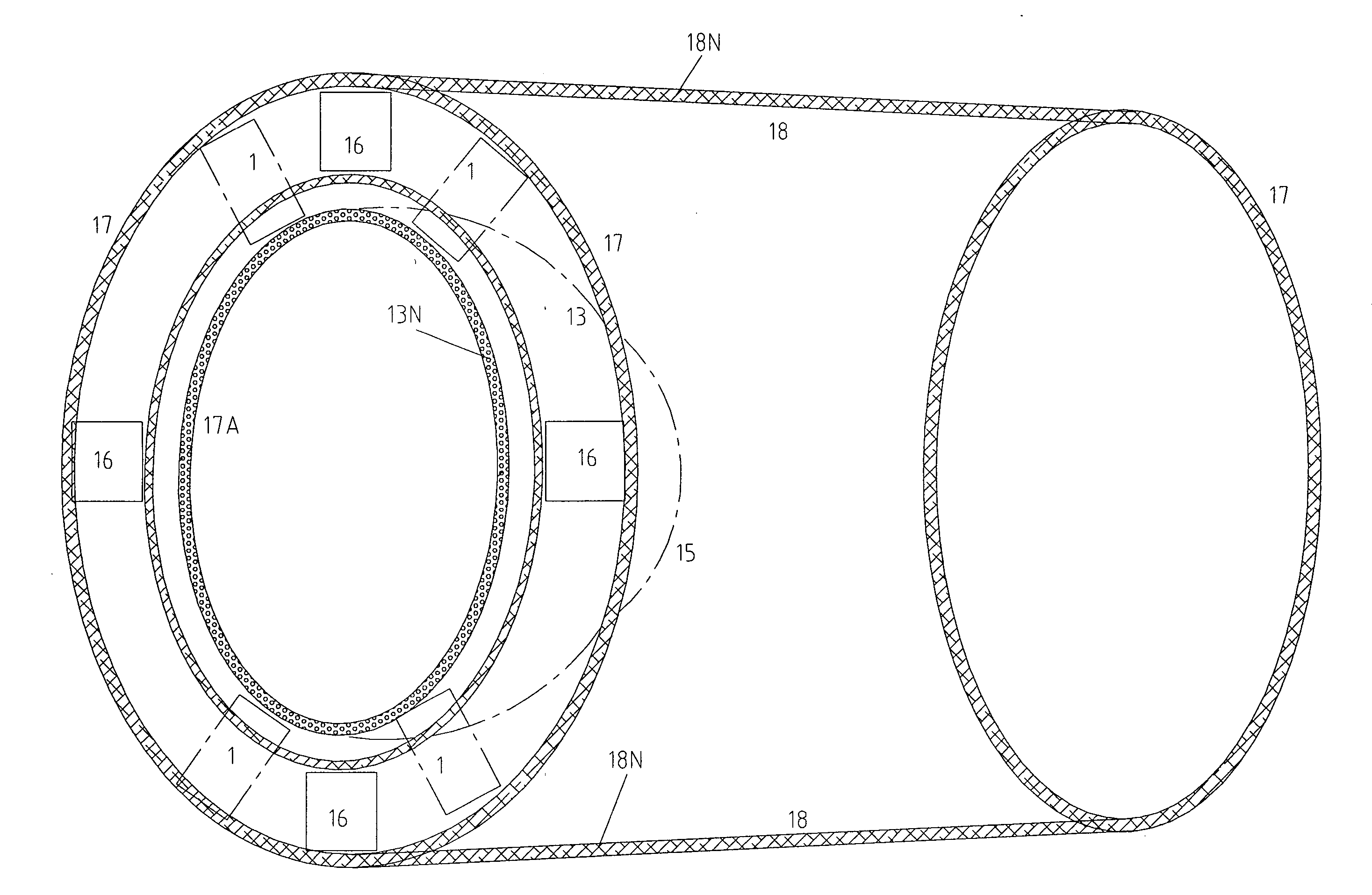
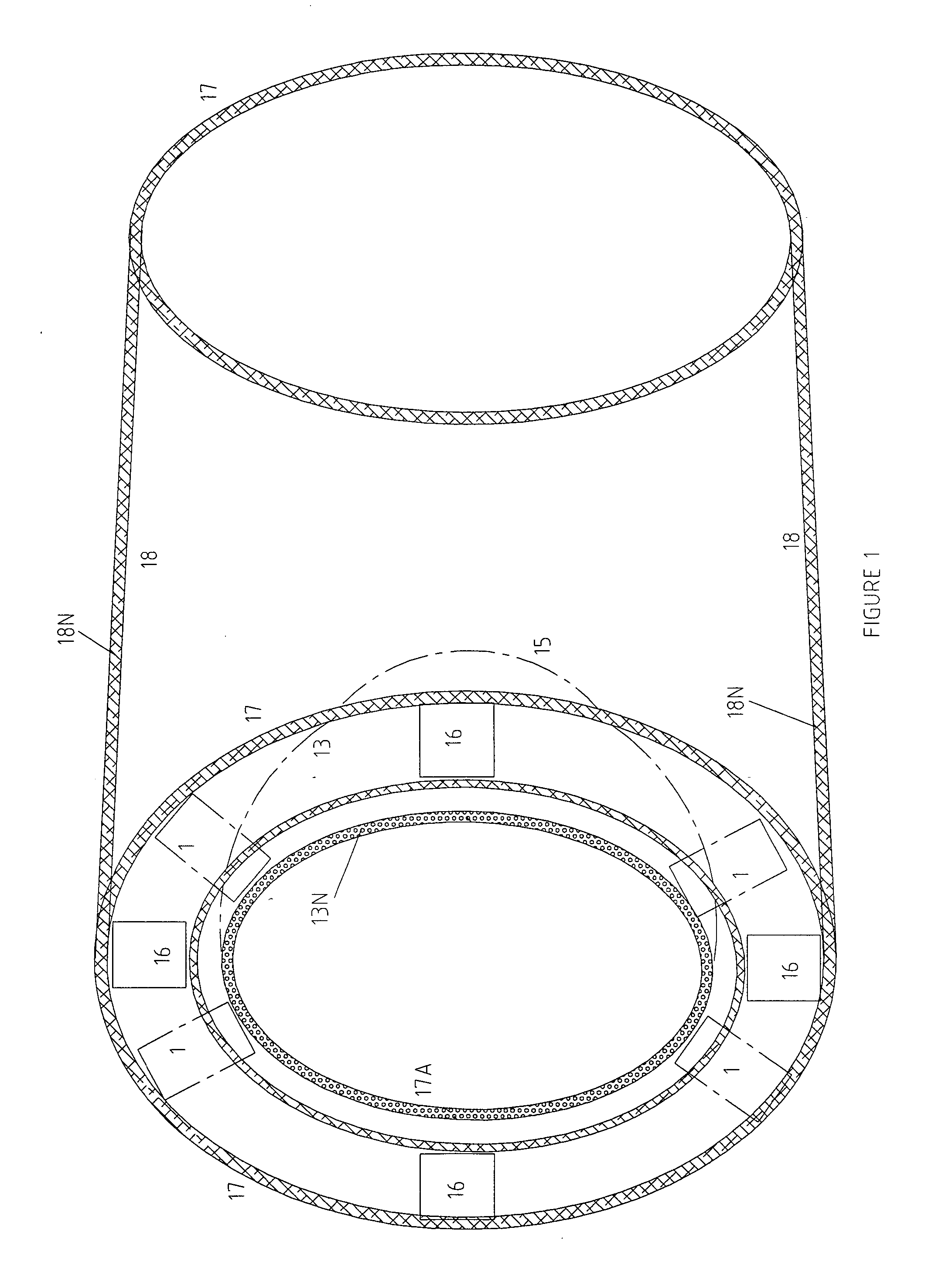
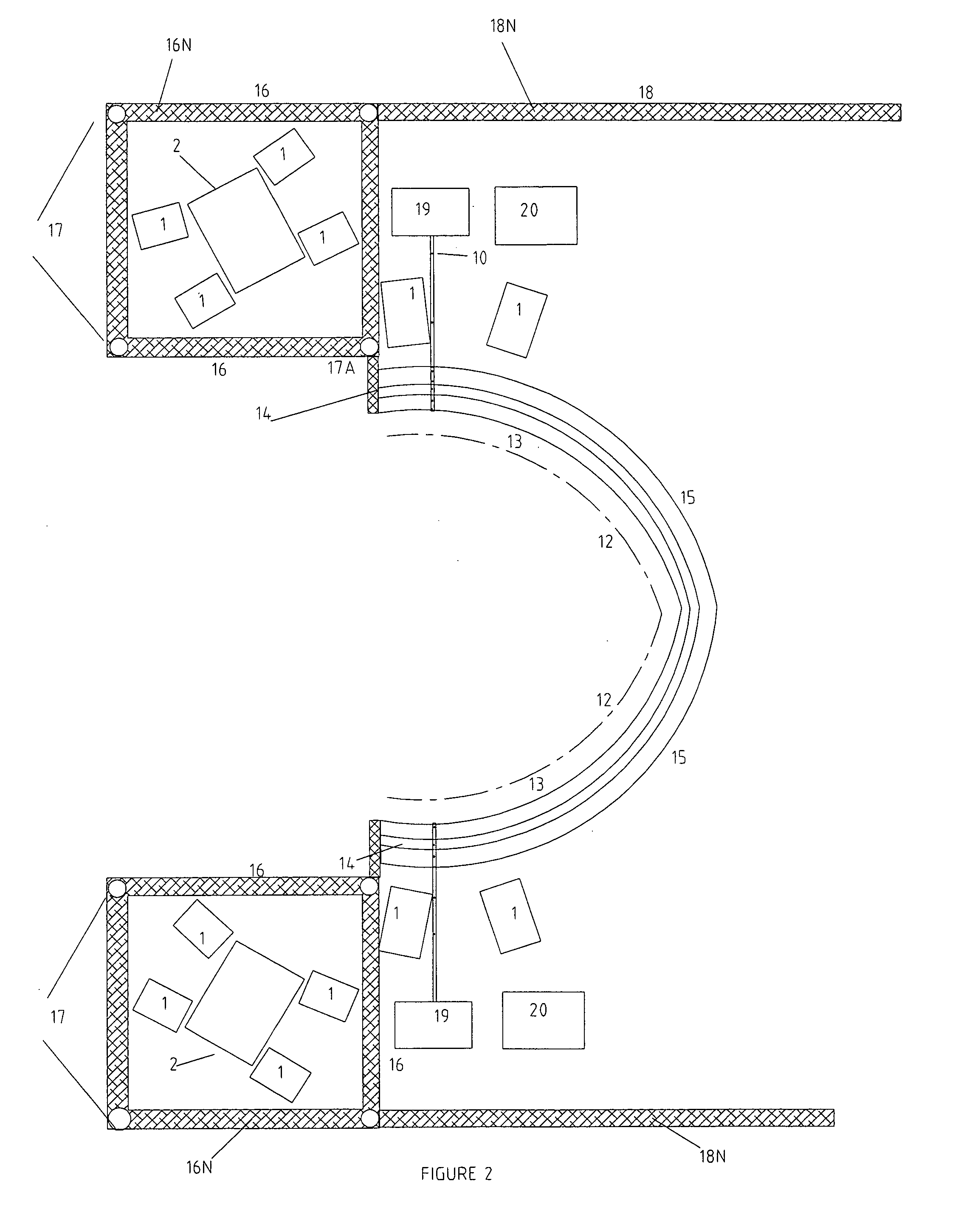
[0049] According with this drawings and in their details the present invention “PROPULSION MOTOR”, has the internal and external motor structures according FIG. 1, that is, from number (14) until number (18) and the parts relative to laser (1)(laser gun, amplifiers, compressors, etc.), that will be from nanostructured materials, with exception from first wall (13), being in present invention from carbon nanotubes (nt-C or buckytubes) (13N) since referenced with before continuation-in-part patent application was altered to carbon-carbon nanostructured. When need the refrigerator system (13A) this being from nanofluids, and second computer simulations using molecular dynamics or lattice Boltzman, among others simulation methods, can be allowable, with temperature control, or external force applied, fluid transport characteristic, that is need in the present motor, less quantity of fluid and less dense, not needing practically fluid storage (13C) in some cases, but of a little reservoi...


PUM


Abstract

A propulsion motor is provided to motor and processes, which combined are the nanostructured materials in all motor structures (17, 17A, 18), applied to the reaction room (16), applied to exhaust vessel (13, 14, 15) and in their details, parts of trigger system (1), applied to reaction vessel (2), all with the intention to become less massive, more mechanical resistant, applied to some processes like z-pinch (2, 4, 4A, 4B), high flux compression generator (4, 4A, 4B, 4C, 4D), using ultra super capacitors (4), conductors nanotubes (4A) as well as some parts of CPA laser (2), all with the intention to become less massive, more mechanical resistant and adequate to each situation.

Description

CROSS-REFERENCE TO RELATED APPLICATIONS [0001] This application is a continuation-in-part of U.S. Ser. No. 11 / 324,544, pending, filed Jan. 3, 2006, which is a continuation-in-part of U.S. Ser. No. 10 / 528,225, pending, which is a national entry application under 35 USC 371 of PCT / BR2003 / 000046 filed Mar. 27, 2003, which claims priority to Brazilian application P10205584-8 filed 19 Sep. 2002. [0002] The instant application is also a continuation-in-part of U.S. Ser. No. 10 / 528,225, pending, which is a national entry application under 35 USC 371 of PCT / BR2003 / 000046 filed Mar. 27, 2003, which claims priority to Brazilian application P10205584-8 filed 19 Sep. 2002. [0003] The instant application also claims priority under 35 USC 119 to Brazilian application C20205584-8 filed Nov. 18, 2005. [0004] U.S. Ser. No. 11 / 324,544, noted above, claims priority under 35 USC 119 to Brazilian application C10205584-8 filed Jan. 3, 2005. [0005] All of the above referenced applications are hereby incor...

Claims


Application Information

Patent Timeline
Patent Type & Authority Applications(United States)
IPC IPC(8): H05H1/22
CPCG21B1/23G21B1/17Y02E30/10
Inventor CONCEICAO, JOSE DA
Owner CONCEICAO JOSE
Learn More