

Use Of An Ammonia Storage Device In Production Of Energy
a technology of ammonia storage and energy, which is applied in the direction of ammonia preparation/separation, ammonia handling/storage, fuel cells, etc., can solve the problems of reducing the application value of ammonia, and reducing the efficiency of ammonia storage and release,
- Summary
- Abstract
- Description
- Claims
- Application Information
AI Technical Summary
Problems solved by technology
Method used
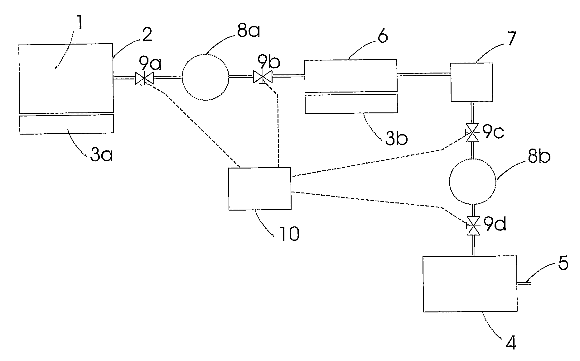
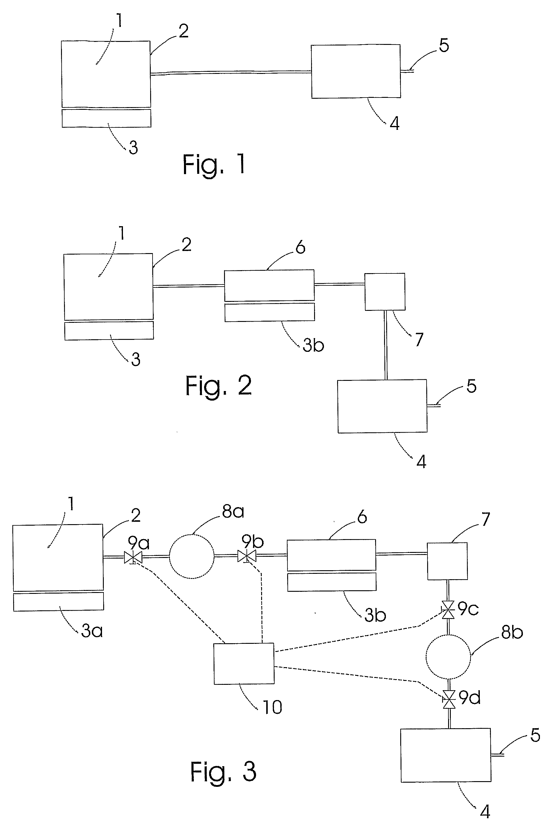
Image

Examples
example 1
Ammonia Desorption from Metal Ammine Halides
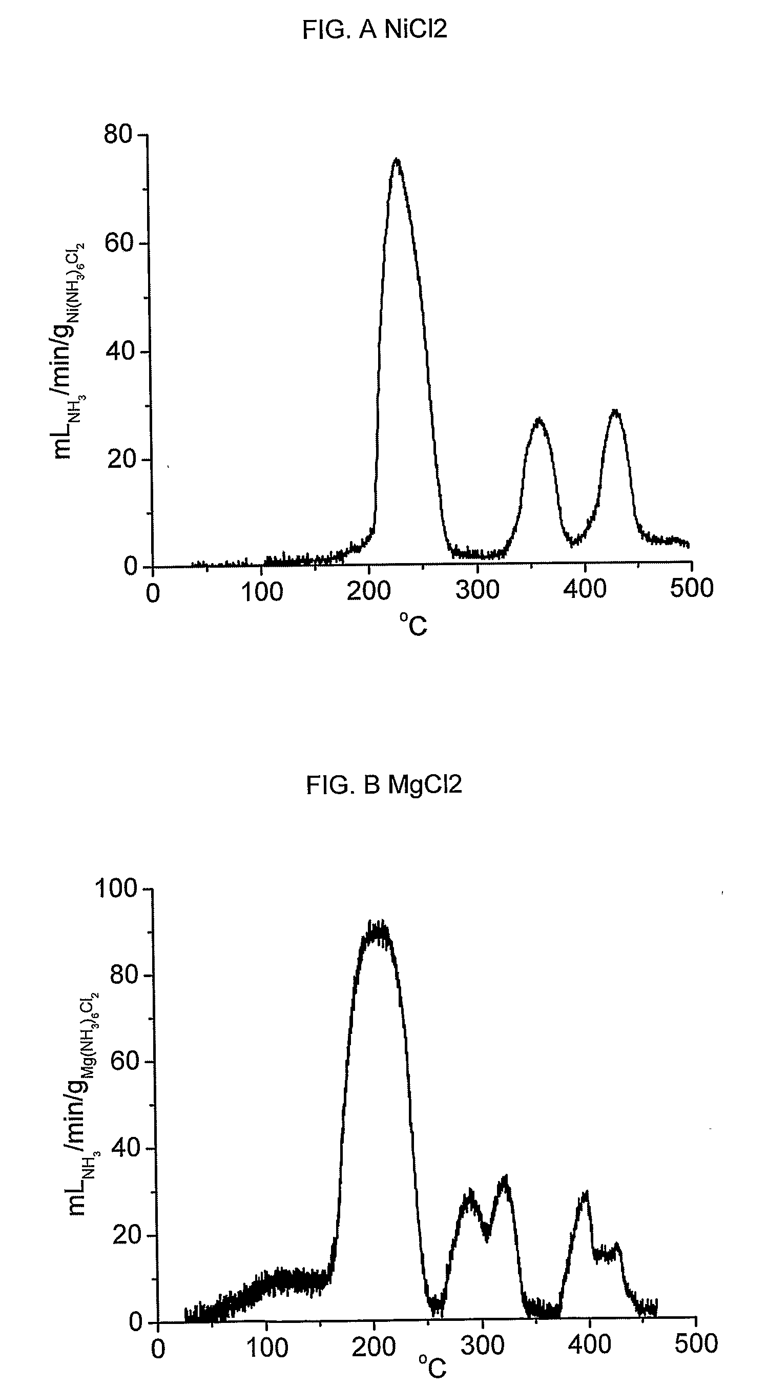
[0093] Absorption of ammonia is exemplified by Ni(NH3)6C12 and Mg(NH3)6Cl2. Release of ammonia from Ni(NH3)6Cl2 was accomplished by placing 1.1 grams of Ni(NH3)6Cl2 in a container of 10 millilitres internal volume equipped with a single outgoing tube connected to flow measuring apparatus. The container was sealed, and heated by resistive electric heating at an increase of temperature of 0.2° C. / min. The resulting flow of ammonia is shown in figure A, and the integral liberated amount constitutes the entire theoretical amount of 6 moles NH3 pr. mole NiCl2 within the measurement error.
[0094] Similar tests were performed with Mg(NH3)6Cl2 to exemplify desorption from alkaline earth metal ammine halides. The resulting flow of ammonia is shown in figure B, and the integral liberated amount again constitutes the entire theoretical amount of 6 moles NH3 pr. mole MgCl2 within the measurement error.
example 2
Uptake of Gaseous Ammonia in Metal Salts of the General Structure MaXz
[0095] Salts of the general formula MaXz were exposed to gaseous ammonia and the absorption was investigated using x-ray diffraction. ZnCl2, CuSO4, COCl3, MgCl2 and NiCl2 were investigated after exposure to gaseous ammonia at 1 bar pressure and room temperature. The results are shown in FIGS. C-G. One further experiment showed that ammonia absorption of MgCl2 was complete in less than 20 min at 8 bar ammonia pressure.
example 3
Reversibility of the Absorption Desorption Cycle
[0096] The reversibility of the absorption cycles were investigated by x-ray diffraction of MgCl2 after absorption and subsequent desorption, FIG. H, and after a second absorption, FIG. 1. When compared with FIG. F it is found that the changes in crystal structure during absorption / desorption of ammonia are reversible.
PUM
| Property | Measurement | Unit |
|---|---|---|
| temperatures | aaaaa | aaaaa |
| temperature | aaaaa | aaaaa |
| density | aaaaa | aaaaa |
Abstract
Description
Claims
Application Information