Combined Fluid-Air Evaporator And Novel Switching Concept For A Heat Pump In A Ventilating Apparatus

a technology of fluid-air evaporator and heat pump, which is applied in the direction of energy-efficient heating/cooling, space heating and ventilation details, domestic heating details, etc., can solve the problems of reducing the service life of the compressor, increasing the complexity of the cooling loop, and increasing the cost of the equipmen

Inactive Publication Date: 2007-09-13
FRAUNHOFER GESELLSCHAFT ZUR FOERDERUNG DER ANGEWANDTEN FORSCHUNG EV
View PDF6 Cites 11 Cited by
  • Summary
  • Abstract
  • Description
  • Claims
  • Application Information

AI Technical Summary

Benefits of technology

[0025] Compact ventilation air conditioners having the combined evaporator are a very efficient solution for use in low energy houses and 3-liter houses due to the advantages described.

Problems solved by technology

Particularly in the case of lower temperatures, at which the cooled building used air flows through the evaporator of the heat pump, icing frequently occurs within the evaporator, through which the function of the heat pump is disadvantageously influenced until breakdown, so that suitable measures are to be taken to counteract corresponding occurrences of icing.
However, for this purpose four-way valves or three-way valves having possible leaks are required within the complicated loop systems in which heat pumps are integrated.
The use of expensive solenoid valves is also known, through which the cooling loop becomes more complicated, more expensive, and more susceptible to breakdown.
In addition, upon changeover between heating and cooling operation of the heat pump, the cooling loop briefly becomes unstable, which results not only in reduction of the performance number of the heat pump, but rather in addition causes reduction of the service life of the compressor.
However, above all in typical air-water heat pumps, the icing of the evaporator represents a large problem.
Thawing must be performed very often below the specified outside temperatures, however, through which the performance number of the heat pump worsens.

Method used


Image

  • Combined Fluid-Air Evaporator And Novel Switching Concept For A Heat Pump In A Ventilating Apparatus
  • Combined Fluid-Air Evaporator And Novel Switching Concept For A Heat Pump In A Ventilating Apparatus
  • Combined Fluid-Air Evaporator And Novel Switching Concept For A Heat Pump In A Ventilating Apparatus

Examples


Embodiment Construction

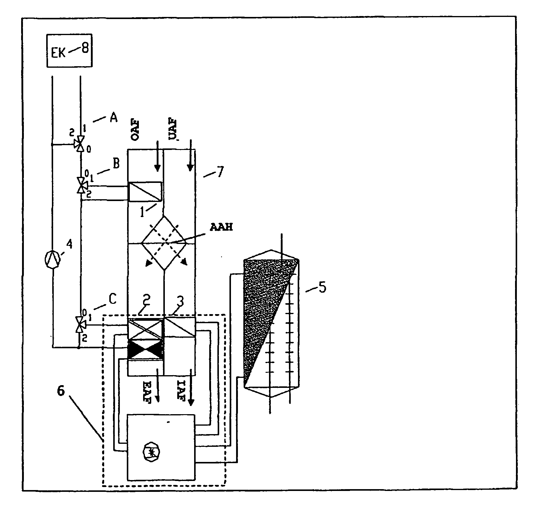
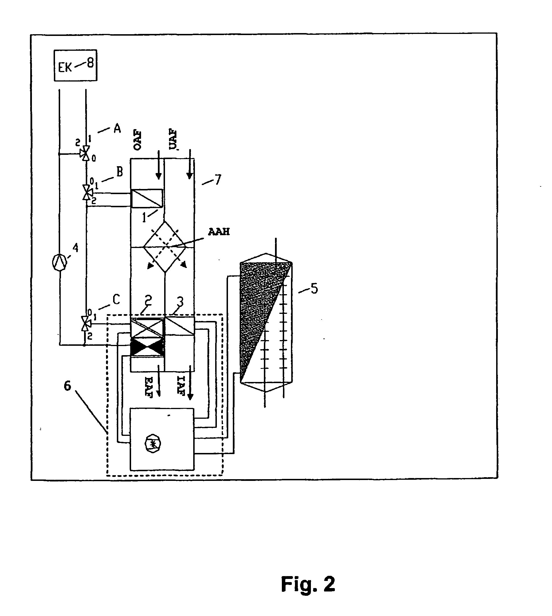
[0008] The present invention is based on the object of specifying an achievement of the object specified above, so that changing over between heating and cooling operation of a heat pump integrated in a building ventilation arrangement is possible using means which are as technically simple as possible to implement. The icing occurring in the known heat pumps is to be largely avoided, and the operational reliability and also the service life of the components participating in the loop of heat pumps are particularly to be improved.

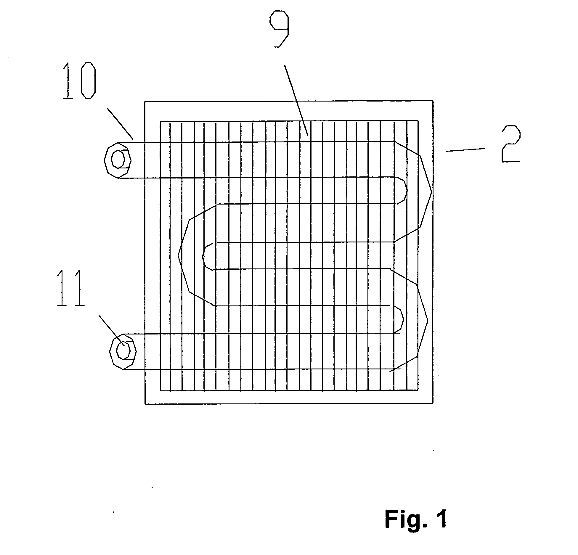
[0009] The achievement of the object on which the present invention is based is specified in Claim 1, which describes a combined fluid-air evaporator, whose use as an evaporator element within a heat pump represents the refinement according to the present invention of a ventilator arrangement for buildings described in Claim 8. Features advantageously refining the idea according to the present invention may be taken from the subclaims and the further descr...


PUM


Abstract

A combined fluid-air evaporator having at least two separate duct systems is described, through which separate material flows may be conducted, at least one of the two duct systems having a free surface which may be brought into thermal contact with an air flow, and the at least two duct systems being at least partially in thermal contact with one another. Furthermore, a ventilation arrangement for a building is described using the combined fluid-air evaporator, in which a used air flow directed out of the building, which is in thermal contact with an outside air flow via an air-air heat exchanger, comes into thermal contact with the combined fluid-air evaporator, through which a refrigerant and an exothermic fluid pass, the refrigerant circulating in the loop of a heat pump, whose condenser is connected downstream in the flow direction from the air-air heat exchanger in the heated outside air flow, and the exothermic fluid circulates in the loop of a heat accumulator system.

Description

TECHNICAL AREA [0001] The present invention relates to a combined fluid-air evaporator, which is preferably usable as a refrigerant evaporator for a ventilation arrangement provided for buildings. For this purpose, the term “fluid” comprises, in the expanded definition, all phase states of materials with the exception of the solid phase, and thus particularly the liquid phase and also the gas phase. A preferred integration of the combined fluid-air evaporator with a heat pump is also described. BACKGROUND INFORMATION [0002] In newly constructed apartment houses, strengthened ventilating apparatuses having heat reclamation are increasingly installed, which result in higher living comfort, since the required air exchange is ensured automatically and the temperature level of the intake air is significantly raised by the heat reclamation. Through the targeted exploitation of the used air heat to preheat the intake air using an air-air heat exchanger, the heating operation for a building...

Claims


Application Information

Patent Timeline
Patent Type & Authority Applications(United States)
IPC IPC(8): F24F12/00F28D7/14F28F1/32
CPCF24F12/006F24F2012/007Y02B30/563F28F1/32F28D7/14Y02B30/56
Inventor BICHLER, CHRISTIANBUHRING, ANDREAS
Owner FRAUNHOFER GESELLSCHAFT ZUR FOERDERUNG DER ANGEWANDTEN FORSCHUNG EV
Why Eureka
Try Eureka