Liquid discharge head and manufacturing method therefor

a technology of liquid discharge head and manufacturing method, which is applied in the direction of printing, etc., can solve the problem of adhesion of the flow path formation member to the substra

Inactive Publication Date: 2007-09-13
CANON KK
View PDF6 Cites 14 Cited by
  • Summary
  • Abstract
  • Description
  • Claims
  • Application Information

AI Technical Summary

Benefits of technology

[0014]While taking into account the problems of the related art, the objective of the present invention is to provide a

Problems solved by technology

H11-348290, the adhesion of the flow path fo

Method used


Image

  • Liquid discharge head and manufacturing method therefor
  • Liquid discharge head and manufacturing method therefor
  • Liquid discharge head and manufacturing method therefor

Examples


first embodiment

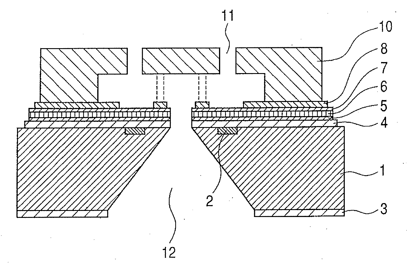
[0049]A liquid discharge head including the structure shown in FIG. 1 was manufactured using the following processes.

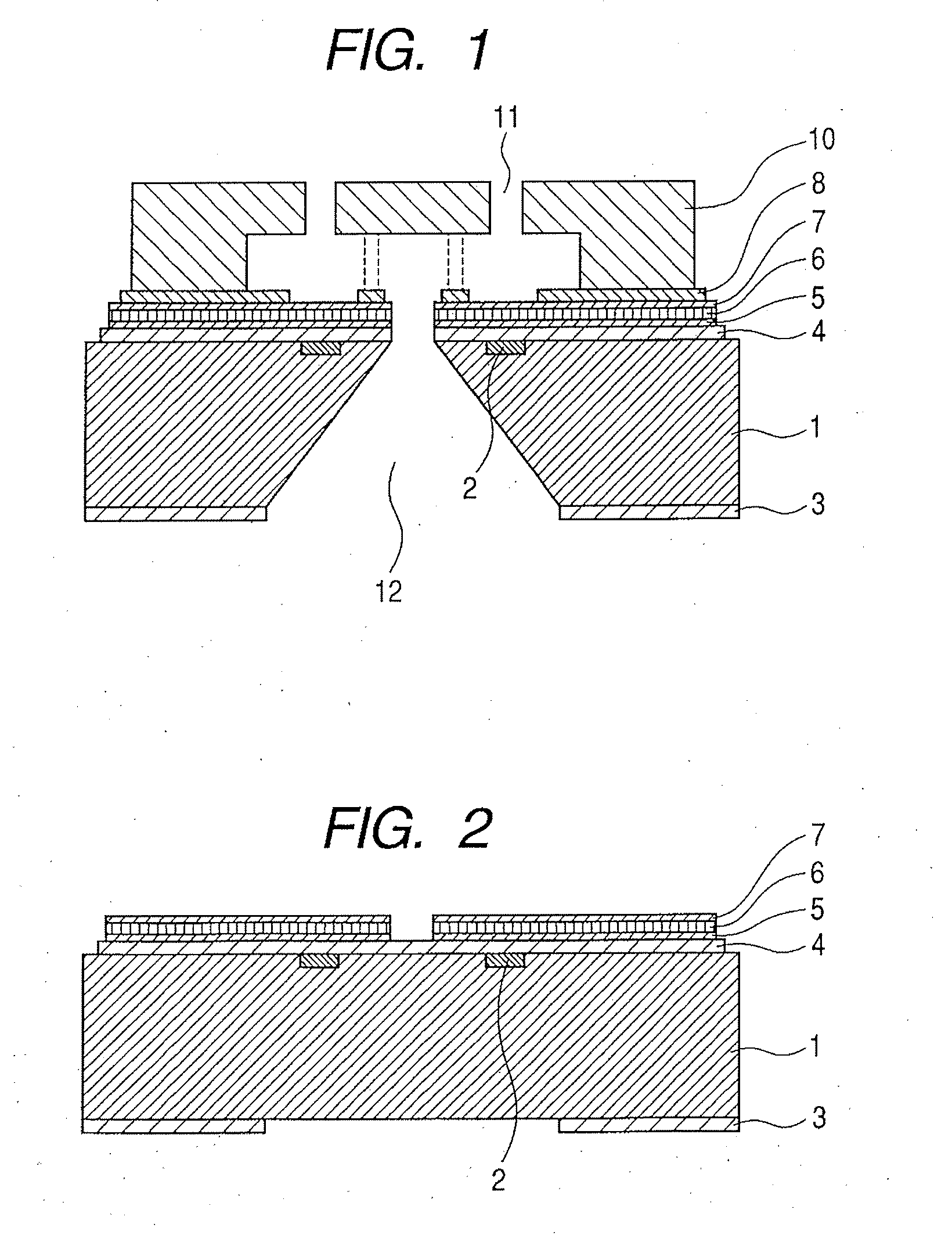
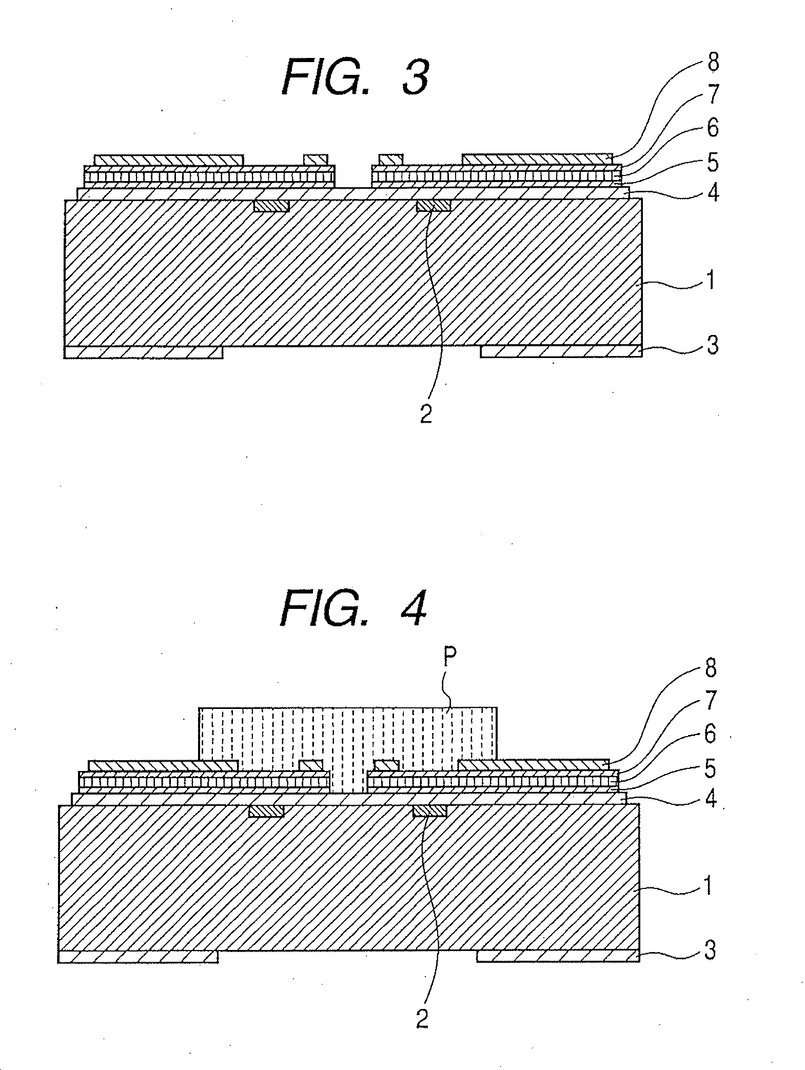
[0050]As shown in FIG. 2, an Si wafer having a crystal lographic axis was employed as a substrate 1, and a mask 3 was formed on the lower face of the substrate 1, leaving a portion that served as an ink supply port 12. Then, on the upper face of the substrate 1, a tantalum nitride layer of about 100 nm, which served as heating resistor layers 2, and control signal input electrodes (not shown) were respectively deposited using sputtering and etching. A silicon nitride layer of 1000 nm was overlaid as a first protective layer 4, using the low temperature plasma CVD method, and as a first adhesive layer 5, a 20 nm titanium layer was deposited on the first protective layer 4 using sputtering. Thereafter, an iridium layer of about 200 nm was formed as a second protective layer 6 using sputtering, and then a 20 nm titanium layer was deposited as a second adhesive layer 7, ...

second embodiment

[0061]After the second protective layer 6 was deposited on the structure in FIG. 1, the same process as in the first embodiment was performed to obtain a liquid discharge head, except that, as a second adhesive layer 7, a titanium nitride layer of about 20 nm was deposited instead of a titanium layer, by the reactive sputtering of nitride while nitrogen was introduced.


PUM


Abstract

A liquid discharge head comprises a substrate, on which are formed energy generating means for generating energy to be used for the discharge of a liquid through a discharge port, and a precious metal protective layer for protecting the energy generating means, an inorganic adhesive layer formed of at least one material selected from titanium, titanium nitride, tantalum nitride and chromium nitride, said inorganic adhesive layer being closely adhered to the precious metal protective layer, an organic adhesive layer made of an organic material, and a flow path formation member, serving as a wall of a flow path communicated with the discharge port. The substrate, the inorganic adhesive layer, the adhesive layer and the flow path formation member are bonded to the substrate in the this order.

Description

BACKGROUND OF THE INVENTION[0001]1. Field of the Invention[0002]The present invention relates to a liquid discharge head mounted on a liquid discharge apparatus and a manufacturing method therefor.[0003]2. Description of the Related Art[0004]A liquid discharge apparatus, such as an ink jet printer, is a system wherein ink is discharged when bubbling is produced by thermal energy generated by an electrothermal transducing element, and can form and record high definition images at high speed. A common configuration used for an ink jet recording head (liquid discharge head) includes: multiple discharge ports, and flow paths that communicate with the discharge ports; and a plurality of electrothermal transducing elements that generate the thermal energy that is used for the discharge of ink. Each of the electrothermal transducing elements includes a heat resistor, and an electrode for supplying power to the heat resistor, that provides insulation between the electrothermal transducing e...

Claims


Application Information

Patent Timeline
IPC IPC(8): B41J2/05
CPCB41J2/14129B41J2/1603B41J2/1628B41J2/1646B41J2/1631B41J2/1639B41J2/1642B41J2/1629
Inventor KITANI, KOJI
Owner CANON KK
Why Eureka
Try Eureka