Infiltration cannula

a cannula and infiltration technology, applied in the field of infiltration cannulas, can solve the problems of excessive tissue distention, discomfort and pain of patients, and achieve the effects of reducing pain, facilitating fluid delivery, and preventing disruption of the infiltration process

Active Publication Date: 2007-09-13
KLEIN JEFFREY A
View PDF69 Cites 30 Cited by
  • Summary
  • Abstract
  • Description
  • Claims
  • Application Information

AI Technical Summary

Benefits of technology

[0055] Multiple infiltration cannulas (e.g., two) may be used simultaneously. Use of multiple infiltration cannulas prevents disruption of the infiltration process when one infiltration cannula is removed and relocated. In particular, a second infiltration cannula may be inserted closely adjacent to a first infiltration cannula which has partially anesthetized the area in which the second infiltration cannula is being inserted to reduce the pain associated with inserting the second infiltration cannula into non anesthetized tissue.

Problems solved by technology

Otherwise, fluid may squirt out of the apertures and onto medical professionals when the cannula needle is moved out too much.
Unfortunately, the piston-like in and out motion of the cannula causes the patient discomfort.
These sharp-tipped tumescent infiltration devices have been associated with puncture-injury to deeper tissues such as the lungs causing pneumothorax or intra-abdominal viscera causing peritonitis.
One significant cause of pain is a continuous in and out motion of the cannula as it moves through non-anesthetized tissue.
Each advance of the cannula through fat causes discomfort and pain.
The second cause of pain is associated with an excessively rapid distention of tissue resulting from a high rate of fluid injection into a relatively small volume of tissue via limited number of holes on the distal tip of the infiltration cannula.
The On-Q® device cannot be inserted through a tiny hole in the skin into subcutaneous tissue.
Therefore the On-Q device cannot achieve infiltration of local anesthesia and prevent post-operative pain in a preemptive fashion.
As described above, repeated injections or piston-like movement of the cannula causes patient discomfort.
Slow continuous infiltration may not be desirable in certain situations.
Furthermore, continuous infiltrations restrict patient movement for extended periods of time which also cause the patient discomfort.
One example is the need for a cannula that permits emergency fluid resuscitation in situations where an IV cannot be established such as nighttime military combat conditions where using a flash light to establish an IV access would be extremely dangerous.
Unfortunately, the Schwartz device requires a sterile high tech hospital environment and demands fluoroscopy and ultrasound guidance.
The intravascular insertion of the catheter via the guidewire is a complex procedure that requires significant clinical training, experience and skill.
This insertion procedure is so specialized that a majority of physicians do not have the requisite expertise to qualify for hospital privileges for inserting an intravascular catheter using a guidewire.
For the small needle embodiment of Schwartz, vascular compression resulting from injecting excessive volume of

Method used


Image

  • Infiltration cannula
  • Infiltration cannula
  • Infiltration cannula

Examples


Embodiment Construction

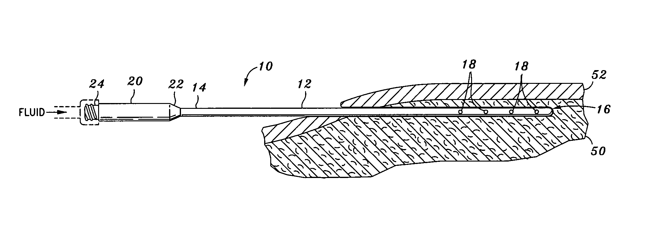
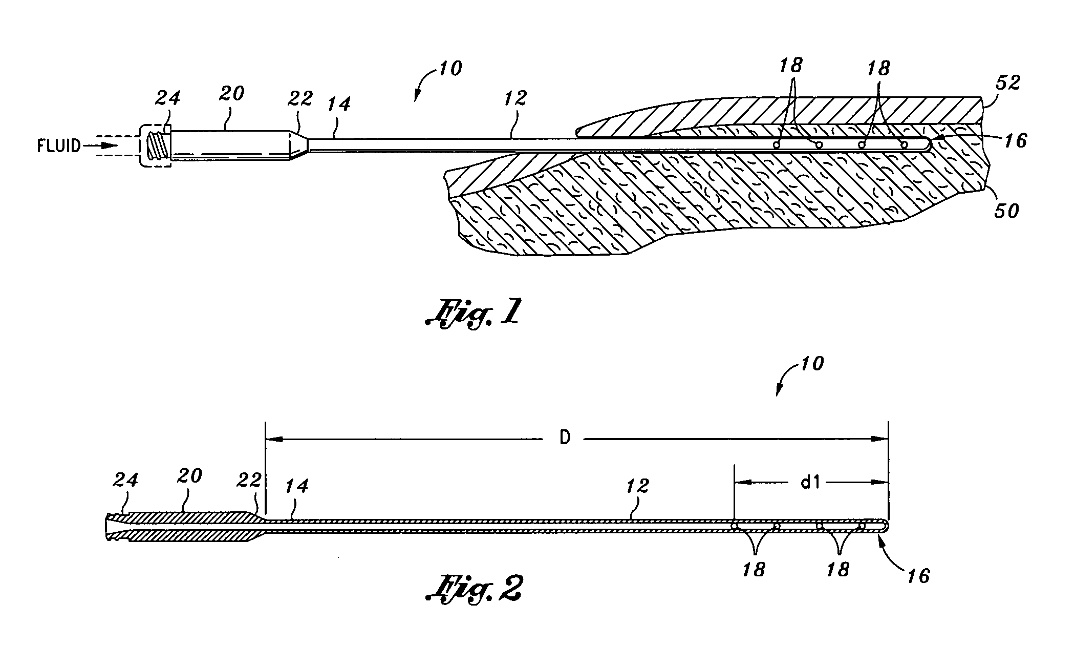
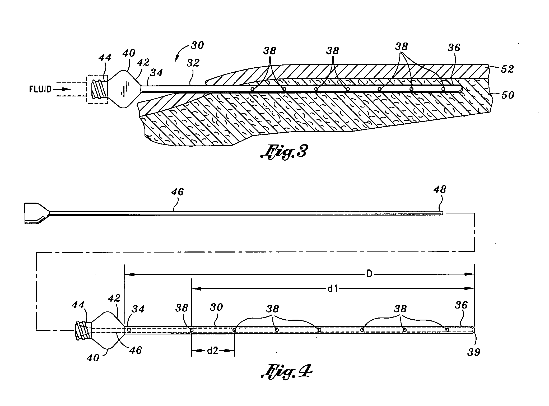
[0066] As described in further detail below, the present invention takes advantage of the tumescent technique in order to provide intermittent or continuous, brief or prolonged multi-liter infiltration of local anesthetic, physiologic fluid, antibiotics or other therapeutic solution with a significant decrease in patient discomfort due to the elimination of the piston-like in and out motion of the cannula. Once the cannula is positioned in place, there is no need to repeatedly move the cannula in and out through the tissue in order to deliver the fluid to a wide area. Using the tumescent technique and stainless steel versions of the present invention, the time needed in order to complete the infiltration of a targeted anatomic area is reduced to nearly half of the time required when using traditional prior art cannulas. The device and method of the present invention can use multiple (e.g., two or more) infiltration cannulas simultaneously. While one cannula is actively dispersing tu...


PUM


Abstract

An infiltration cannula and method of using the infiltration cannula during a tumescent infiltration procedure are disclosed herein. The infiltration cannula may have an outwardly flaring hub which may be wedged into an adit of a patient to minimize leakage of fluid being infiltrated into the patient. Also, the infiltration cannula may be utilized to hydrate a dehydrated patient by a medically untrained person. The infiltration cannula may also be used to deliver an antibiotic/vasoconstrictive drug solution to minimize surgical site infections.

Description

CROSS-REFERENCE TO RELATED APPLICATIONS [0001] The present application is a continuation-in-part application of pending U.S. Ser. No. 10 / 877,566, filed Jun. 21, 2004, which is a continuation-in-part application of Applicant's prior U.S. Ser. No. 10 / 442,370 filed May 21, 2003 entitled INFILTRATION CANNULA, and is related to pending U.S. patent application Ser. No. 10 / 877,337, filed Jun. 25, 2004, the disclosures of which are expressly incorporated herein by reference.STATEMENT RE: FEDERALLY SPONSORED RESEARCH / DEVELOPMENT [0002] Not Applicable BACKGROUND OF THE INVENTION [0003] The present invention relates in general to an infiltration cannula permitting the infiltration of very large volumes of tumescent fluid in a safe and painless manner. [0004] Definitions: [0005] infiltration: an injection that causes a fluid to permeate or percolate through pores or interstices. Thus an infiltration refers to an injection directly into tissue. [0006] infusion: an injection that pours a fluid in...

Claims


Application Information

Patent Timeline
IPC IPC(8): A61M25/06
CPCA61M5/158A61M5/3291A61M37/00A61M25/0097A61M25/007
Inventor KLEIN, JEFFREY A.
Owner KLEIN JEFFREY A
Why Eureka
Try Eureka