System and method for improving performance of a fluid sensor for an internal combustion engine

a technology of fluid sensor and internal combustion engine, which is applied in the field of system and method for improving the performance of fluid sensor for internal combustion engine, can solve the problems of inability to detect non-uniform soot distribution using perimeter mounted sensors, inability to meet real-time or near-real-time sensing, and inability to meet packaging requirements, etc., to improve sensor performance, improve sensor performance, and improve the effect of emissions control and fuel economy

Active Publication Date: 2007-09-20
FORD GLOBAL TECH LLC
View PDF20 Cites 45 Cited by
  • Summary
  • Abstract
  • Description
  • Claims
  • Application Information

AI Technical Summary

Benefits of technology

[0009] A system and method for improving sensor performance while sensing a predetermined component of a fluid flowing through a pipe include a closed-ended structure for extending into the exhaust pipe and having at least one inlet for receiving fluid flowing through the pipe and at least one outlet generally opposite the at least one inlet relative to the direction of fluid flow, wherein the structure passively redirects substantially all fluid flowing from the at least one inlet to the at least one outlet toward the sensor to provide a representative sample of the bulk fluid to the sensor.
[0012] The present invention provides a number of advantages. For example, the present invention provides a sensor boss that can be used with currently available sensors to improve sensor performance by redirecting a representative cross-section of fluid flowing through a pipe toward the sensor. Providing a boss independent of the sensor also allows a common sensor to be used in applications having different flow profiles or exhaust pipe diameters. The present invention may be used to provide passive cooling of the exhaust gas or other fluid prior to reaching an associated sensor. The present invention does not require a device to extract the exhaust sample, such as a vacuum pump. Improved sensor performance associated with the present invention may result in improved emissions control and fuel economy.

Problems solved by technology

However, the present inventors have recognized that the presence or concentration of the component measured by the sensor may not be uniformly distributed across the diameter of the exhaust pipe for some applications or operating conditions.
Similarly, for diesel applications using a soot sensor positioned downstream of a particulate filter, soot generated by a crack in the filter, for example, may produce a localized, non-uniform soot distribution difficult to detect using a perimeter mounted sensor.
While this approach works well for research and development efforts, the additional complexity, cost, and packaging requirements are not amenable to real-time or near real-time sensing of exhaust flow on-board a vehicle.

Method used


Image

  • System and method for improving performance of a fluid sensor for an internal combustion engine
  • System and method for improving performance of a fluid sensor for an internal combustion engine
  • System and method for improving performance of a fluid sensor for an internal combustion engine

Examples


first embodiment

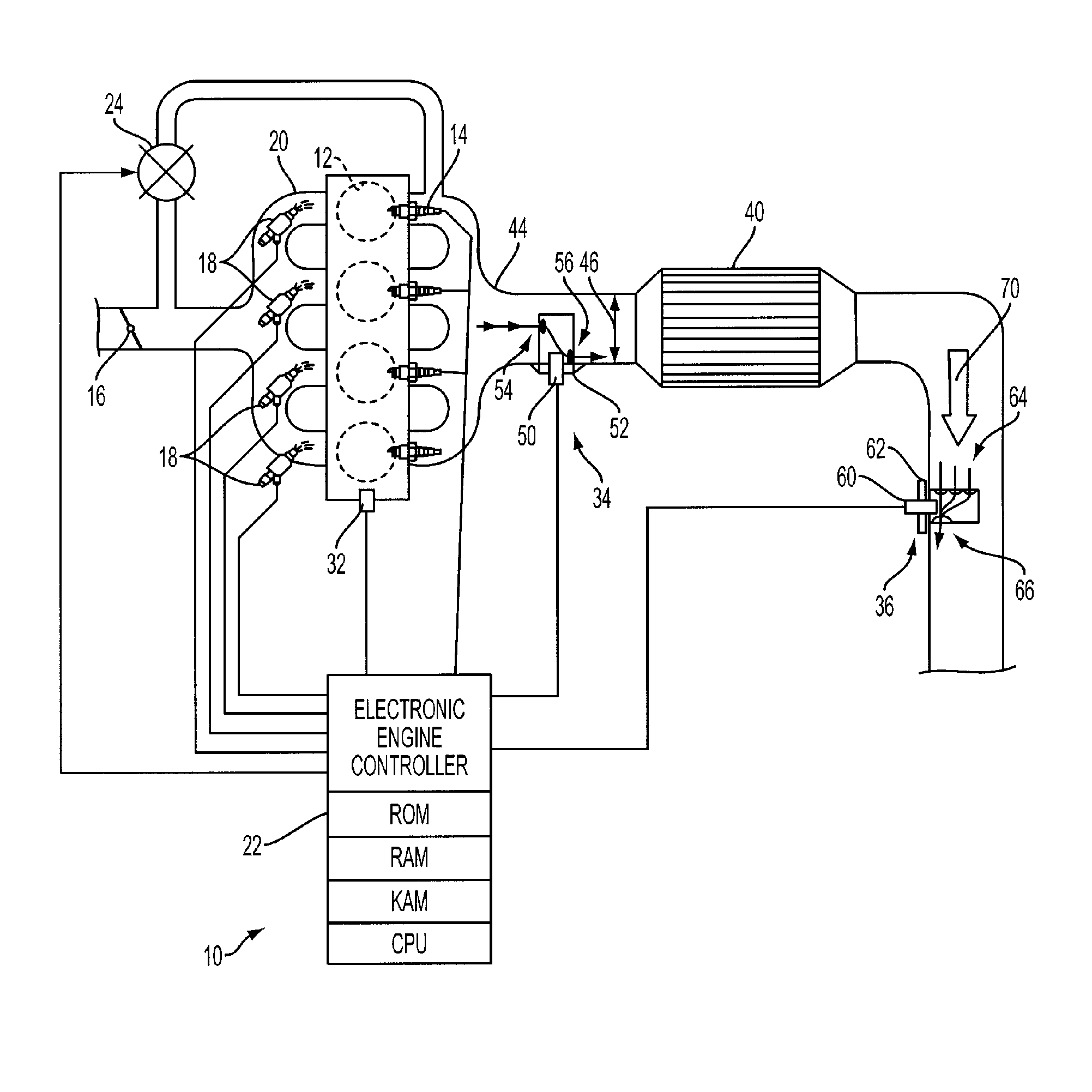
[0019] In the representative application illustrated in FIG. 1, sensor assembly 34 includes a device for improving sensor performance according to the present invention and is positioned upstream of an exhaust treatment or after-treatment device 40, which generally represents any of a number of known devices / systems that may be used alone or in combination in various applications, such as three-way catalysts (TWC), lean NOx traps (LNT), urea / SCR (selective catalytic reactor or reduction converter) systems, particulate filters, and the like. As such, sensor assembly 34 may include a sensor 50 for detecting presence or concentration of one or more elements or substances in the bulk exhaust flow passing through exhaust pipe or tube 44 from the internal combustion engine. Representative sensors may include HEGO, UEGO, soot, ammonia, and NOx sensors, for example. Sensor 50 is mounted in an open end of a sensor boss 52 that extends into exhaust pipe 44 a distance based on the expected rad...

second embodiment

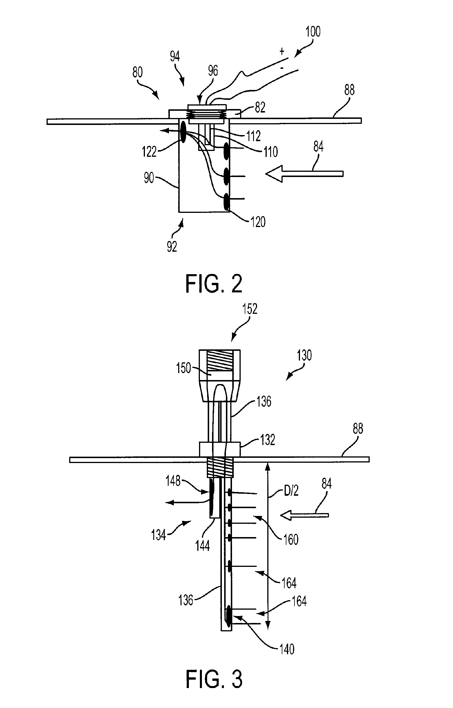
[0020] Sensor assembly 36 includes a device for improving sensor performance according to the present invention and is positioned downstream of exhaust treatment or after-treatment device 40. Sensor 60 is mounted within sensor boss 62 that includes a structure extending into exhaust pipe 44 having a plurality of inlets 64 for receiving exhaust gas from bulk flow 70 and passively redirecting exhaust gas passing through inlets 64 to an outlet 66. As illustrated in FIG. 1, inlets 64 are generally positioned facing upstream with outlet 66 positioned generally opposite inlets 64 so that substantially all of the exhaust gas flowing through the structure flows toward sensor 60 to provide a representative sample or cross-section of bulk flow 70 flowing through pipe 44. The structure extending into the exhaust pipe 44 has a length sufficient to position at least one inlet 64 at a desired sampling location. For detectable substances such as ammonia that may have a temperature dependent distri...


PUM

PropertyMeasurementUnit
distanceaaaaaaaaaa
lengthaaaaaaaaaa
structureaaaaaaaaaa

Abstract

A system and method for improving sensor performance of an on-board vehicle sensor, such as an exhaust gas sensor, while sensing a predetermined substance in a fluid flowing through a pipe include a structure for extending into the pipe and having at least one inlet for receiving fluid flowing through the pipe and at least one outlet generally opposite the at least one inlet, wherein the structure redirects substantially all fluid flowing from the at least one inlet to the sensor to provide a representative sample of the fluid to the sensor before returning the fluid through the at least one outlet.

Description

STATEMENT OF GOVERNMENT INTEREST [0001] The U.S. Government may have a paid-up license in this invention and the right in limited circumstances to require the patent owner to license others on reasonable terms as provided for by the terms of Contract No. DE-FC26-01NT41103 awarded by The Department of Energy.BACKGROUND OF THE INVENTION [0002] 1. Field of the Invention [0003] The present invention relates to systems and methods for improving the performance of sensors used to monitor the exhaust of an internal combustion engine. These gas or fluid sensors include exhaust gas and soot sensors. [0004] 2. Background Art [0005] Exhaust gas and other fluid sensors are used for both control and monitoring of internal combustion engines including vehicles powered by gasoline or diesel fuel and using various engine technologies, such as lean-burn, for example. Various types of gas or fluid sensors may include heated exhaust gas oxygen (HEGO) or lambda sensors, universal exhaust gas oxygen (UE...

Claims


Application Information

Patent Timeline
Patent Type & Authority Applications(United States)
IPC IPC(8): G01N33/00
CPCF01N13/008F01N13/18F01N2570/18F01N2560/02F01N2560/026F01N2450/24
Inventor KUBINSKI, DAVIDZAWACKI, GARRY
Owner FORD GLOBAL TECH LLC
Why Eureka
Try Eureka