
Electrostatic chuck and producing method thereof

a technology of electrostatic chuck and chuck, which is applied in the direction of electrostatic holding devices, basic electric elements, electric devices, etc., can solve the problems of deteriorating the detachment smoothness level of the substrate from the electrostatic chuck, generating more than required leak current, and deteriorating the detachment smoothness level of the substrate, so as to reduce the generation of particles, and reduce the excess leak current

Inactive Publication Date: 2007-09-20
NGK INSULATORS LTD
View PDF10 Cites 30 Cited by
  • Summary
  • Abstract
  • Description
  • Claims
  • Application Information

AI Technical Summary

Benefits of technology

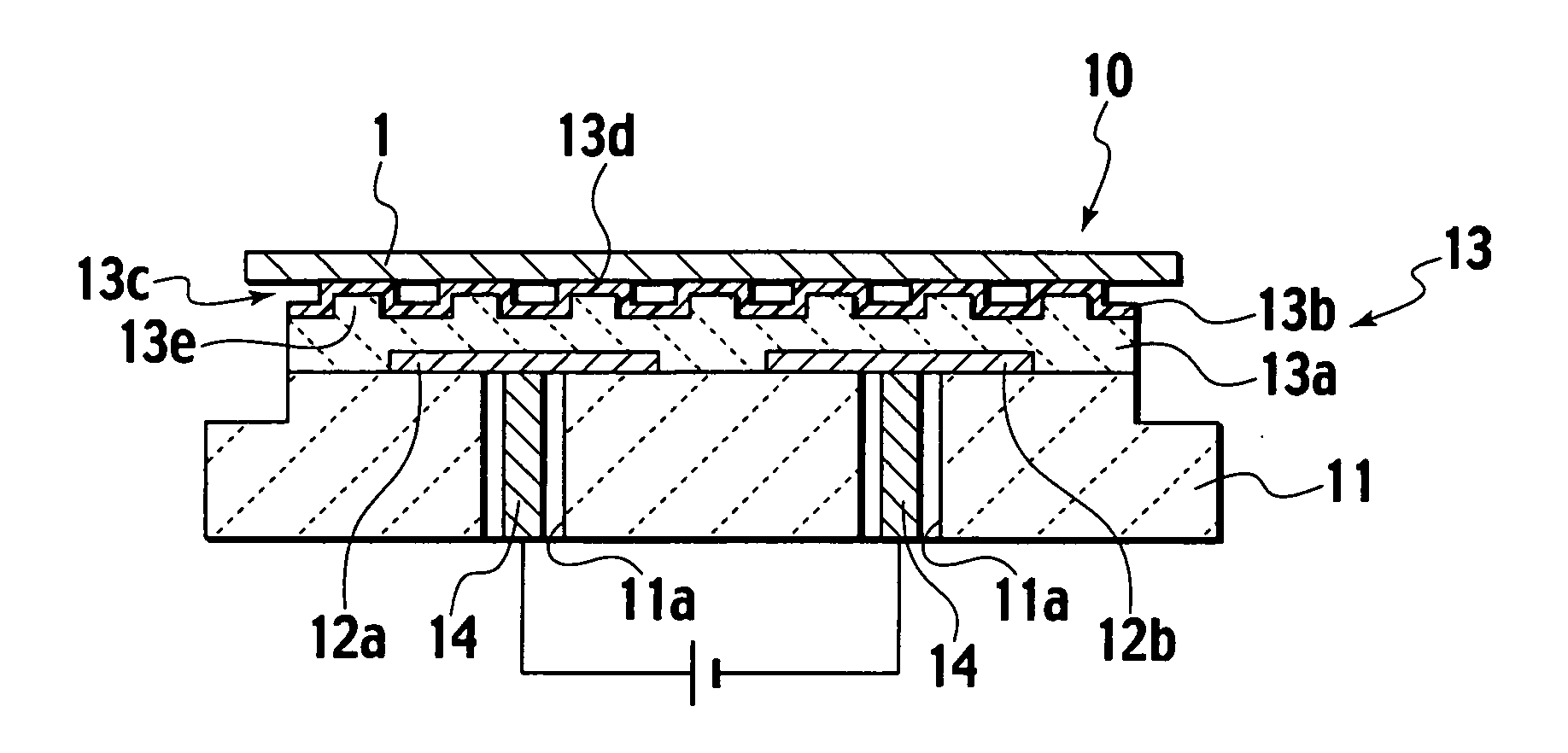
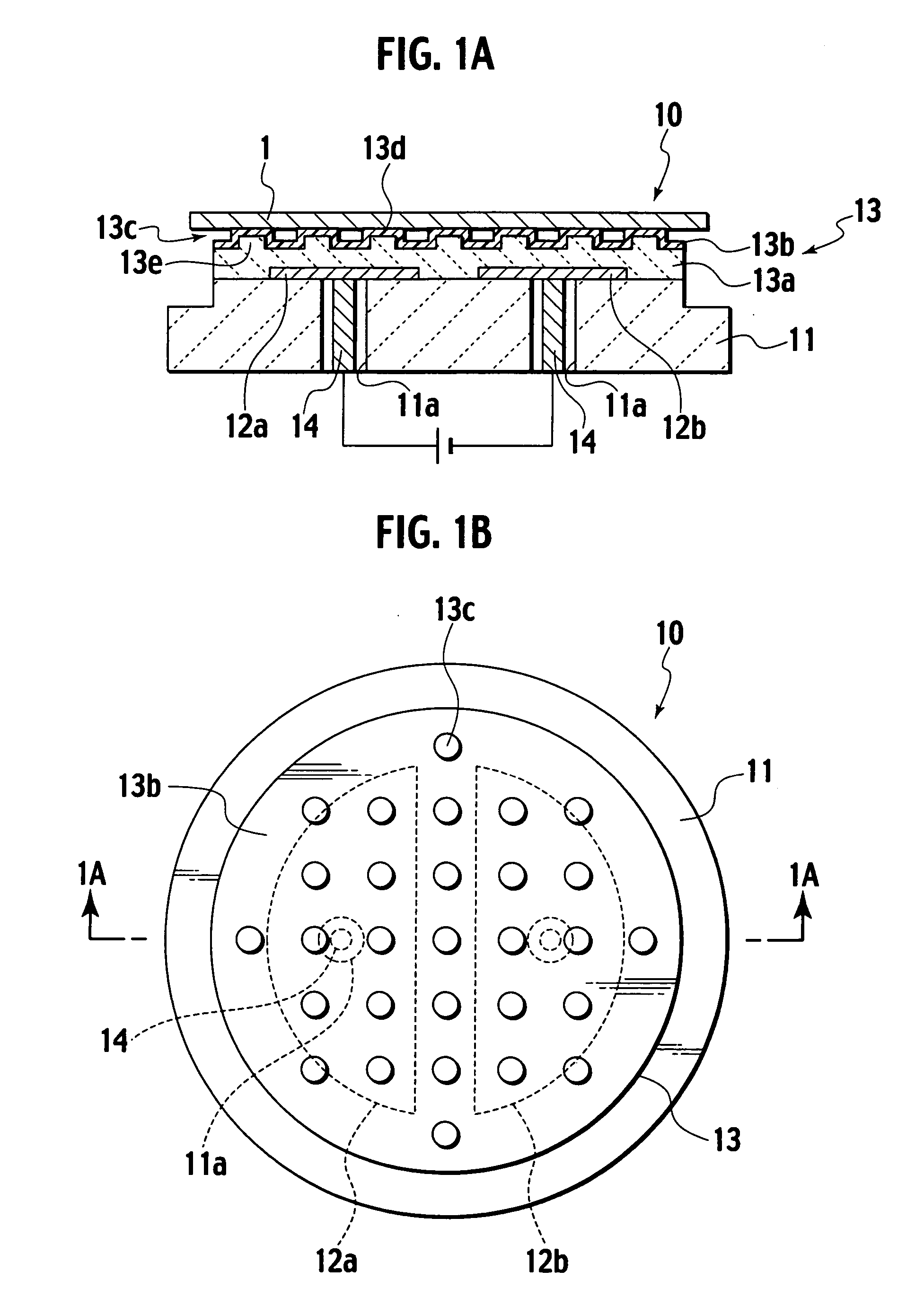
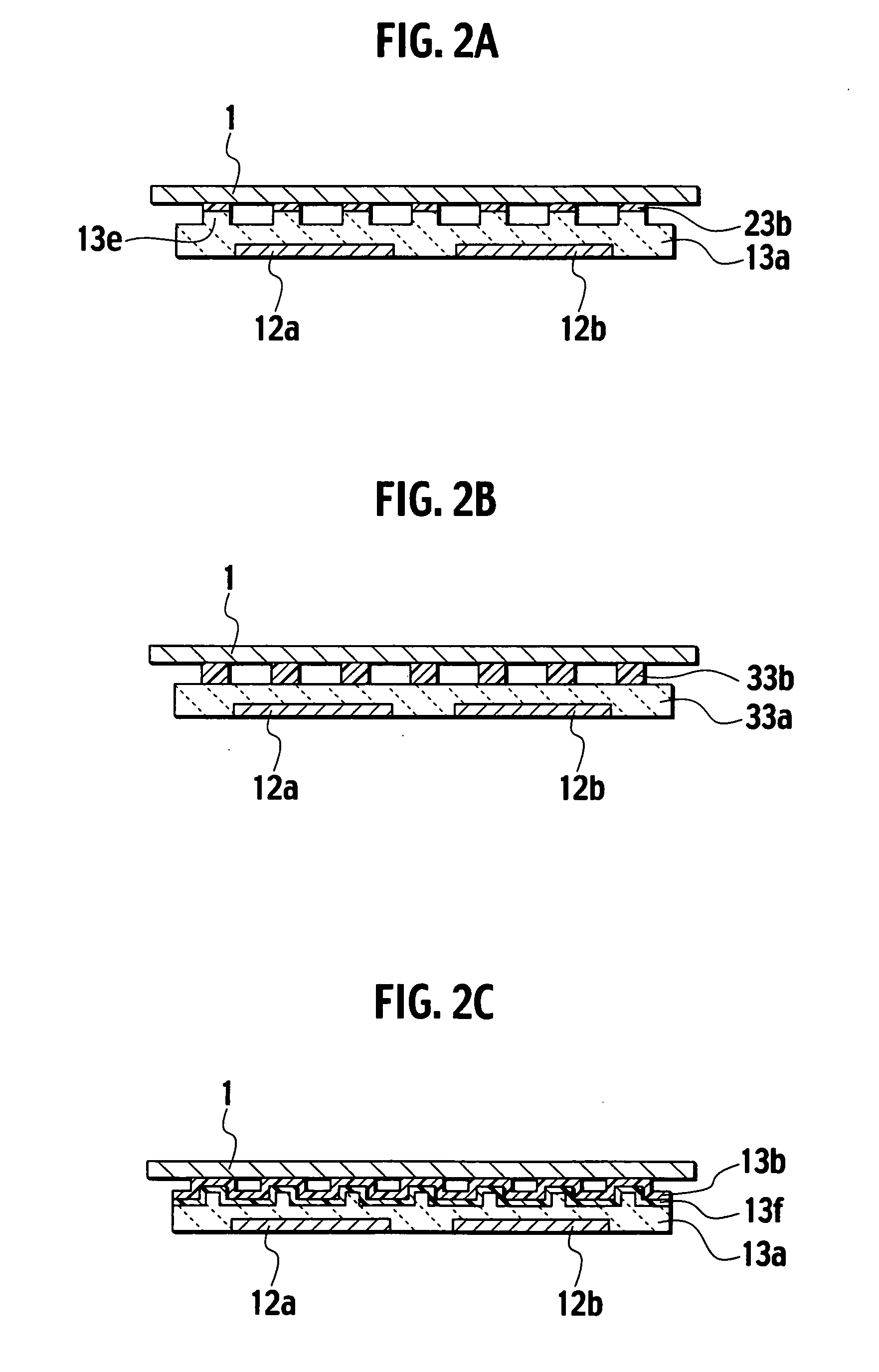
[0013] The electrostatic chuck as described above can use the resin layer on the ceramics layer to suppress the generation of excessive leak current. The dielectric material layer has a superior corrosion resistance owing to the ceramics layer on the inner layer side and the condition of the surface does not change owing to the resin layer on the surface layer side even when the electrostatic chuck is used for a long time. Thus, the electrostatic chuck can maintain the adsorption characteristic for a long period of time.
[0021] According to the present invention, such an electrostatic chuck using the Johnson-Rahbek force can be provided that suppresses excessive leak current from being generated, that maintains the adsorption characteristic for a long time, that improves the detachment smoothness level of a substrate therefrom, and that reduces the generation of particles.

Problems solved by technology

This dielectric material layer made of polyimide resin is inferior to a dielectric material layer made of ceramics in the corrosion resistance and heat resistance, which deteriorates an electrostatic chuck including the dielectric material layer made of polyimide resin.
However, the electrostatic chuck having the ceramics-made dielectric material layer and using the Johnson-Rahbek force has been involved with a risk where excessive and more than required leak current may be generated.
Furthermore, electric charge tends to remain in the ceramics-made dielectric material layer even when voltage application to the electrode is stopped, deteriorating the detachment smoothness level of a substrate from the electrostatic chuck.
Furthermore, when the ceramics-made dielectric material layer is in friction with the substrate, the ceramics-made dielectric material layer tends to scratch the back face of the substrate, which may cause particles.

Method used


Image

  • Electrostatic chuck and producing method thereof
  • Electrostatic chuck and producing method thereof
  • Electrostatic chuck and producing method thereof

Examples


example

[0073] Next, the present invention is described in further detail by an example. However, the present invention is not limited to the following example.

[0074] As raw material powders for ceramics, mixed powders of aluminum nitride powders (95 wt %) and yttrium oxide powders (sintering agent) (5 wt %) were prepared. The ceramics raw powders were added with binder and were mixed by a ball mill to provide slurry. The resultant slurry was dried by a spray drier to provide granulated powders. The resultant granulated powders were molded by a metallic molding method into a compact having a plate-like shape. The compact was fired by the hot press method in nitrogen gas atmosphere. Specifically, the compact was fired at 1860° C. for 6 hours while being pressurized.

[0075] Next, printing paste was prepared by mixing mixed powders of tungsten (W) (80 wt %) and aluminum nitride powders (20 wt %) with ethylcellulose as a binder. An electrode was formed on the surface of the aluminum nitride si...


PUM

PropertyMeasurementUnit
volume resistivityaaaaaaaaaa
thicknessaaaaaaaaaa

Abstract

An electrostatic chuck using the Johnson-Rahbek force, comprising: a dielectric material layer including a ceramics layer and a resin layer formed on the ceramics layer; and an electrode for generating an electrostatic adsorption power.

Description

CROSS-REFERENCE TO RELATED APPLICATION [0001] This application is based upon and claims the benefit from the prior Japanese Application No. 2006-057811, filed on Mar. 3, 2006; the entire contents of which are incorporated herein by reference. BACKGROUND OF THE INVENTION [0002] 1. Field of the Invention [0003] The present invention relates to an electrostatic chuck and a producing method thereof. [0004] 2. Description of the Related Art [0005] Conventional processes for manufacturing semiconductors and liquid crystal have used an electrostatic chuck that adsorbs and retains a semiconductor substrate and a glass substrate. An electrostatic chuck is classified to the one that uses the Coulomb force to adsorb a substrate and the one that uses the Johnson-Rahbek force to adsorb a substrate. The Coulomb force is an electrostatic adsorption power generated between a substrate placed on a surface of a dielectric material layer of an electrostatic chuck and an electrode of the electrostatic ...

Claims


Application Information

Patent Timeline
Patent Type & Authority Applications(United States)
IPC IPC(8): H01T23/00
CPCH02N13/00H01L21/6833H01L21/683H01L21/687
Inventor OHTA, MITSURUTORIGOE, TAKERUIMAI, YASUYOSHI
Owner NGK INSULATORS LTD
Learn More