
Hybrid plasma reactor

a plasma reactor and hybrid technology, applied in the field of plasma reactors, can solve the problems of ccp plasma reactors that are problematic in hardware design and cost, cannot control the concentration of excessive radicals, and cannot control so as to reduce the plasma ion energy

Inactive Publication Date: 2007-09-27
DMS CO LTD
View PDF5 Cites 21 Cited by
  • Summary
  • Abstract
  • Description
  • Claims
  • Application Information

AI Technical Summary

Benefits of technology

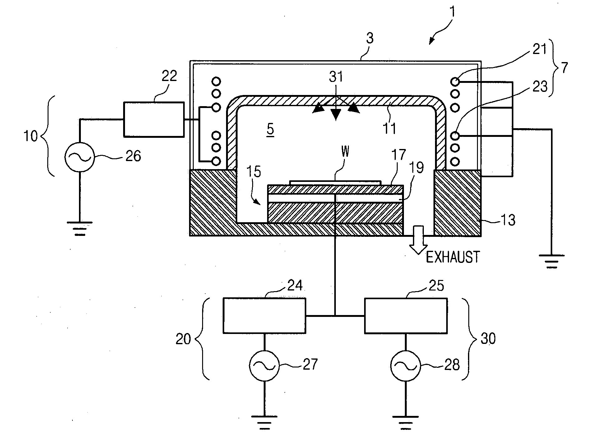
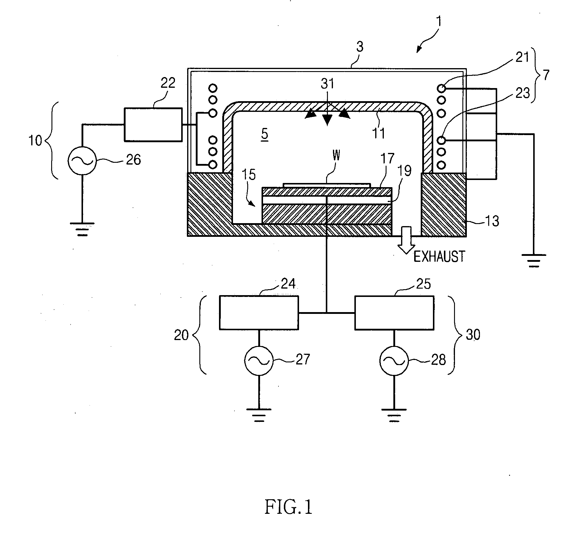
[0010]An aspect of exemplary embodiments of the present invention is to address at least the problems and / or disadvantages and to provide at least the advantages described below. Accordingly, an aspect of exemplary embodiments of the present invention is to provide a hybrid plasma reactor for supplying a bias RF power, which is a mixture of a high frequency RF power and a low frequency RF power, to a cathode and controlling a source power supplied to an antenna coil, thereby compensating a sudden reduction of plasma ion energy caused by an increase of the source power and sustaining plasma ion density and energy within a set range, when the low frequency RF power is supplied to the cathode.

Problems solved by technology

However, the CCP type plasma reactor leads to process kit damage caused by ion impact, and leads to arcing problem caused by high plasma potential because of its characteristic.
The CCP type plasma reactor is problematic in hardware design and cost required for supplying a high frequency power to the upper electrode or the cathode.
However, an ICP type plasma reactor created up to now can generate high density plasma ions, but cannot control a concentration of excessive radicals, control plasma ion energy, and expand a plasma ion energy distribution.
Therefore, the ICP type plasma reactor shows a poorer process performance than the CCP type plasma reactor though it is more effective than the CCP type plasma reactor.
As a result, the ICP type plasma reactor is difficult to perform a high aspect ratio process while guaranteeing a high PhotoResist (PR) selectivity.

Method used


Image

  • Hybrid plasma reactor
  • Hybrid plasma reactor
  • Hybrid plasma reactor

Examples


Embodiment Construction

[0034]Exemplary embodiments of the present invention will now be described in detail with reference to the annexed drawings. In the following description, a detailed description of known functions and configurations incorporated herein has been omitted for conciseness.

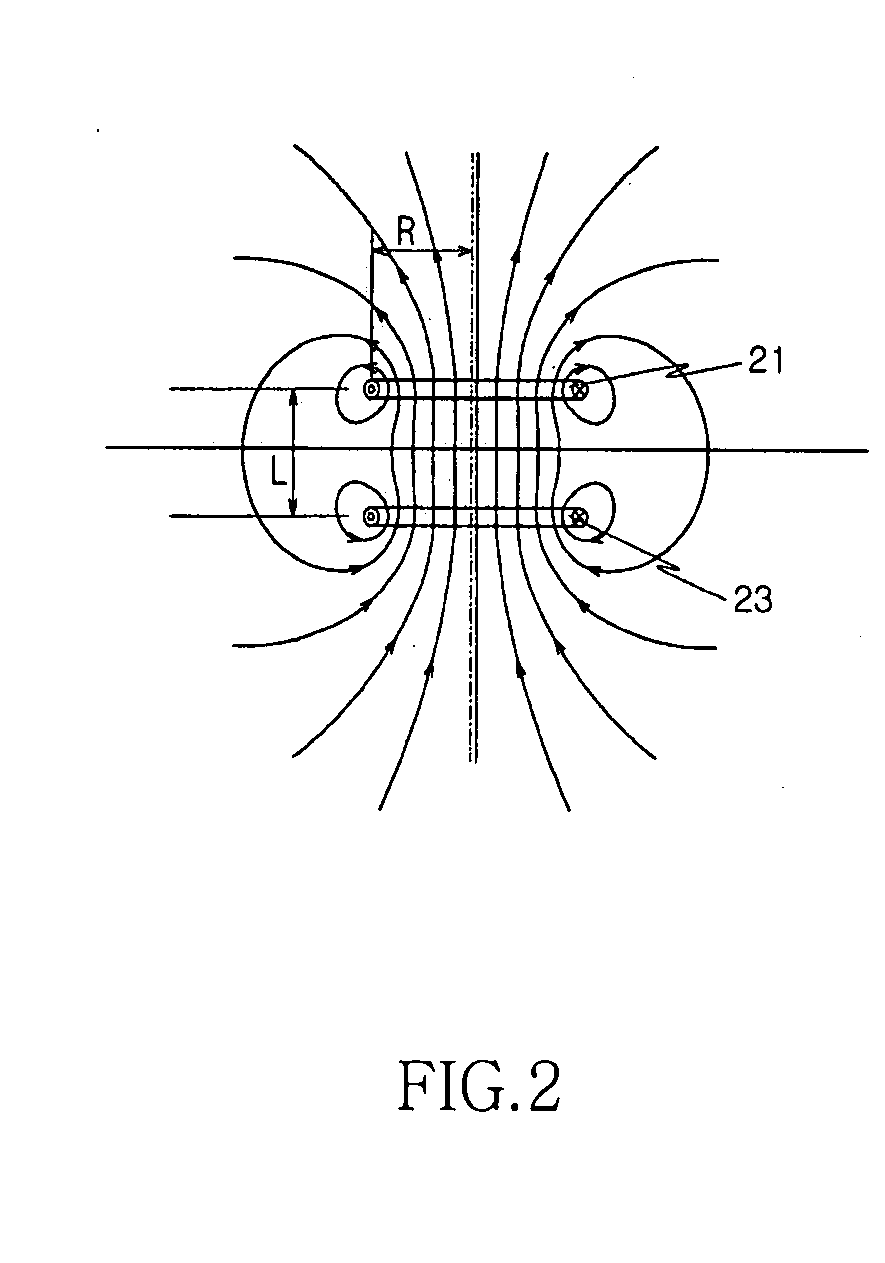
[0035]The present invention is to provide a hybrid type plasma generating apparatus and method for providing plasma properties (e.g., tunable plasma ion density, tunable ion energy distribution, tunable ion energy, tunable radical, and low ion damage plasma) required for a process of fabricating a semiconductor, a Liquid Crystal Diode (LCD), and other integrated circuits. These plasma properties can be controlled using a multi antenna coil structure, a cylinder type dielectric window, an Inductively Coupled Plasma (ICP) source unit provided above a chamber, and a mixture frequency bias applied to a cathode.

[0036]FIG. 1 illustrates a construction of a plasma reactor according to a first exemplary embodiment of the prese...


PUM

PropertyMeasurementUnit
diameteraaaaaaaaaa
RF poweraaaaaaaaaa
internal pressureaaaaaaaaaa

Abstract

Provided is a hybrid plasma reactor. The hybrid plasma reactor includes an ICP (Inductively Coupled Plasma) source unit and a bias RF (Radio Frequency) power supply unit. The ICP source unit includes a chamber, an antenna coil unit, and a source power supply unit. The chamber includes a chamber body whose top is opened and a dielectric window covering the opened top of the chamber body. The antenna coil unit is disposed outside of the dielectric window. The source power supply unit supplies a source power to the antenna coil unit. The bias RF power supply unit supplies a bias RF power to a cathode. The cathode is installed within the chamber and mounts a target wafer on its top.

Description

BACKGROUND OF THE INVENTION[0001]1. Field of the Invention[0002]The present invention relates to a device used in a semiconductor fabrication process, and more particularly, to a plasma reactor.[0003]2. Description of the Related Art[0004]In general, a plasma reactor performing a dry etch process using plasma is classified into a Capacitively Coupled Plasma (CCP) type plasma reactor and an Inductively Coupled Plasma (ICP) type plasma reactor, depending on a method for generating plasma within a chamber. As known in the art, in the CCP type plasma reactor, ion flux energy proportionally increases within a plasma chamber as a frequency of a Radio Frequency (RF) power supplied to an upper electrode or a cathode gets lower. Also, in the CCP type plasma reactor, ion density increases as the frequency of the RF power supplied to the upper electrode or the cathode gets higher. In the ICP type plasma reactor, low dissociation condition and high dissociation condition can be provided within ...

Claims


Application Information

Patent Timeline
Patent Type & Authority Applications(United States)
IPC IPC(8): C23F1/00
CPCH01J37/32091H01J37/321H01L21/67069H01L21/31116H01J37/32165H01L21/02H01L21/3065
Inventor LEE, WEON-MOOK
Owner DMS CO LTD
Learn More