Vibrational circular dichroism spectrometer using reflective optics

a circular dichroism and spectrometer technology, applied in the field of vibrational circular dichroism spectrometer using reflective optics, can solve the problems of time needed to generate high-quality vcd spectrum, measurement is prone to noise and artifacts, scans can take significant time to execute, etc., to achieve high-quality (high signal-to-noise) vcd measurements, increase light throughput, and improve the effect of light captur

Inactive Publication Date: 2007-09-27
THERMO ELECTRONICS SCI INSTR LLC
View PDF3 Cites 25 Cited by
  • Summary
  • Abstract
  • Description
  • Claims
  • Application Information

AI Technical Summary

Benefits of technology

[0009]As implied by the foregoing discussion, the VCD spectrum is preferably obtained with use of no or few refractive elements (e.g., lenses and prisms), with the arrangement shown in the FIGURE using only mirrors (reflective elements) between the light source 102 and the modulator 112, and between the sample cell 110 and the detector 118. (The polarizer 116 and photoelastic modulator 114, as well as the sample cell 110—particularly its windows B may inherently provide refractive effects.) This is contrary to conventional VCD spectrometry arrangements, wherein the use of lenses (typically zinc selenide or barium fluoride lenses) is preferred because artifacts are believed to arise from the use of reflective elements. Despite the use of reflective elements in the spectrometer 100, it has nonetheless been found to provide very high-quality (high signal-to-noise) VCD measurements more quickly than in conventional arrangements, presumably because (1) the use of reflective elements rather than refractive elements increases light throughput to the sample 10, as well as to the detector 118, and allows higher light capture therefrom, with corresponding higher strength in output signals; and (2) collimation of the light input to the modulator 112 is believed to reduce effects such as surface reflection, vignetting, and polarization retardation (elliptical polarization), and thus measurement artifacts are reduced. Additionally, the spectrometer 100 has greater spectral range than conventional arrangements, most likely because refractive elements can attenuate or cut off light in certain wavelength ranges, whereas reflective elements reduce or eliminate such attenuation. Further, owing to the greater strength (higher signal-to-noise) of the signal measured at the detector 118, fewer scans (wavelength or retardation sweeps of the input light) are needed to compile a strong, well-defined VCD spectrum, which can reduce data collection time by as much as two orders of magnitude. As a result, accurate VCD measurement in kinetic or transient conditions—that is, VCD measurement on samples whose properties may rapidly change along the path of the input beam B can in some cases be possible.

Problems solved by technology

However, VCD spectrometry has numerous drawbacks, some of the most significant being the very small magnitude of the VCD signal from a sample to be analyzed (on the order of 104-10−5 absorbance units), and the tendency for measurements to be prone to noise and artifacts (which arise in part owing to the 16w signal magnitude).
An associated problem is the time needed to generate a high-quality VCD spectrum: owing to the low signal-to-noise ratio (SNR) in conventional VCD arrangements, VCD measurements must usually be generated in multiple scans (i.e., repeated measurements must be taken), with the measurements then being averaged or otherwise processed to achieve better SNR.
These scans can take significant time to execute, with scans sometimes requiring several hours, which is inconvenient.
Further, as a result of the need for numerous scans (and significant scan times), VCD measurements of “transient” samples—samples which change over time, e.g., reacting mixtures—are usually not feasible.

Method used


Image

  • Vibrational circular dichroism spectrometer using reflective optics
  • Vibrational circular dichroism spectrometer using reflective optics

Examples


Embodiment Construction

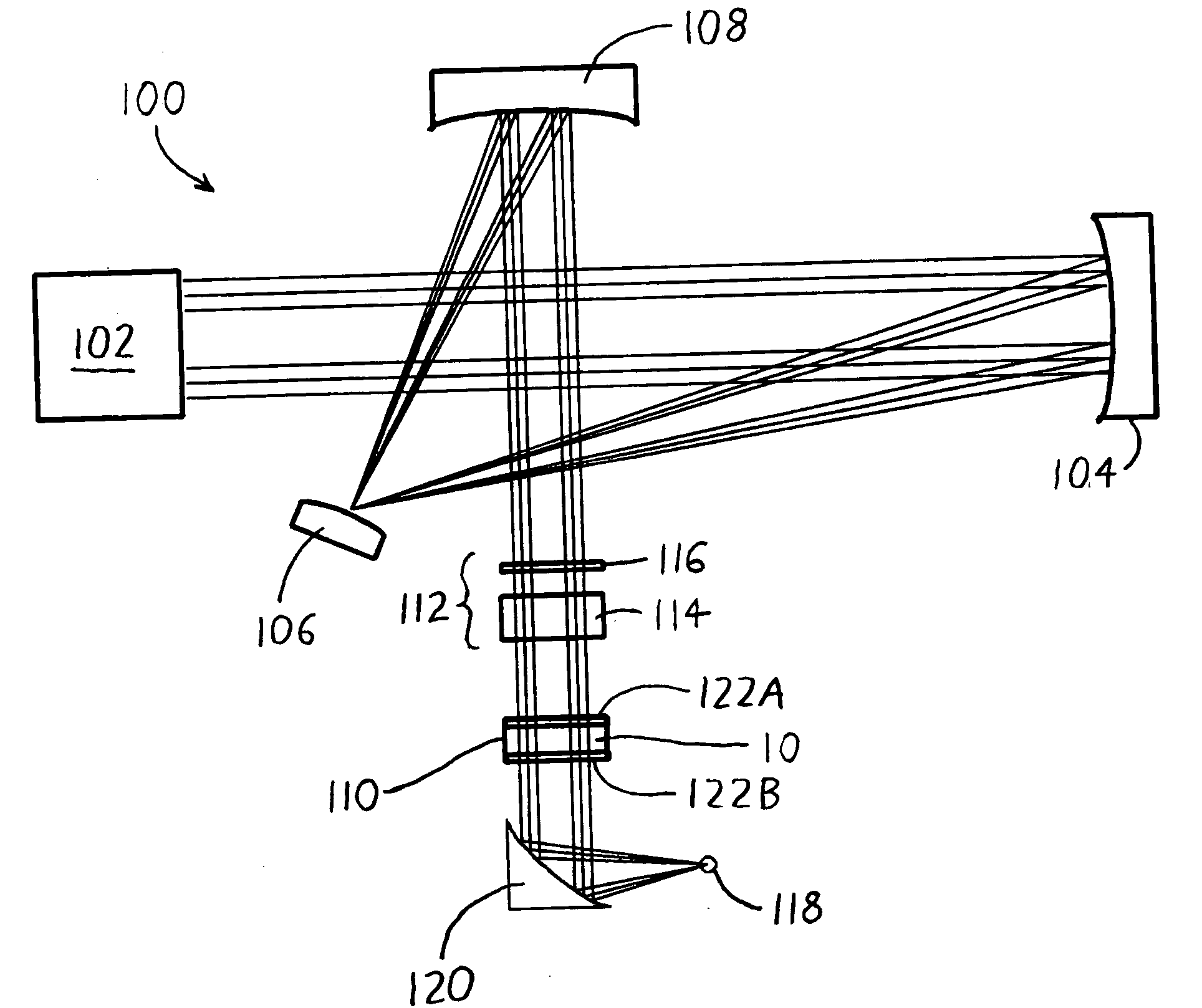
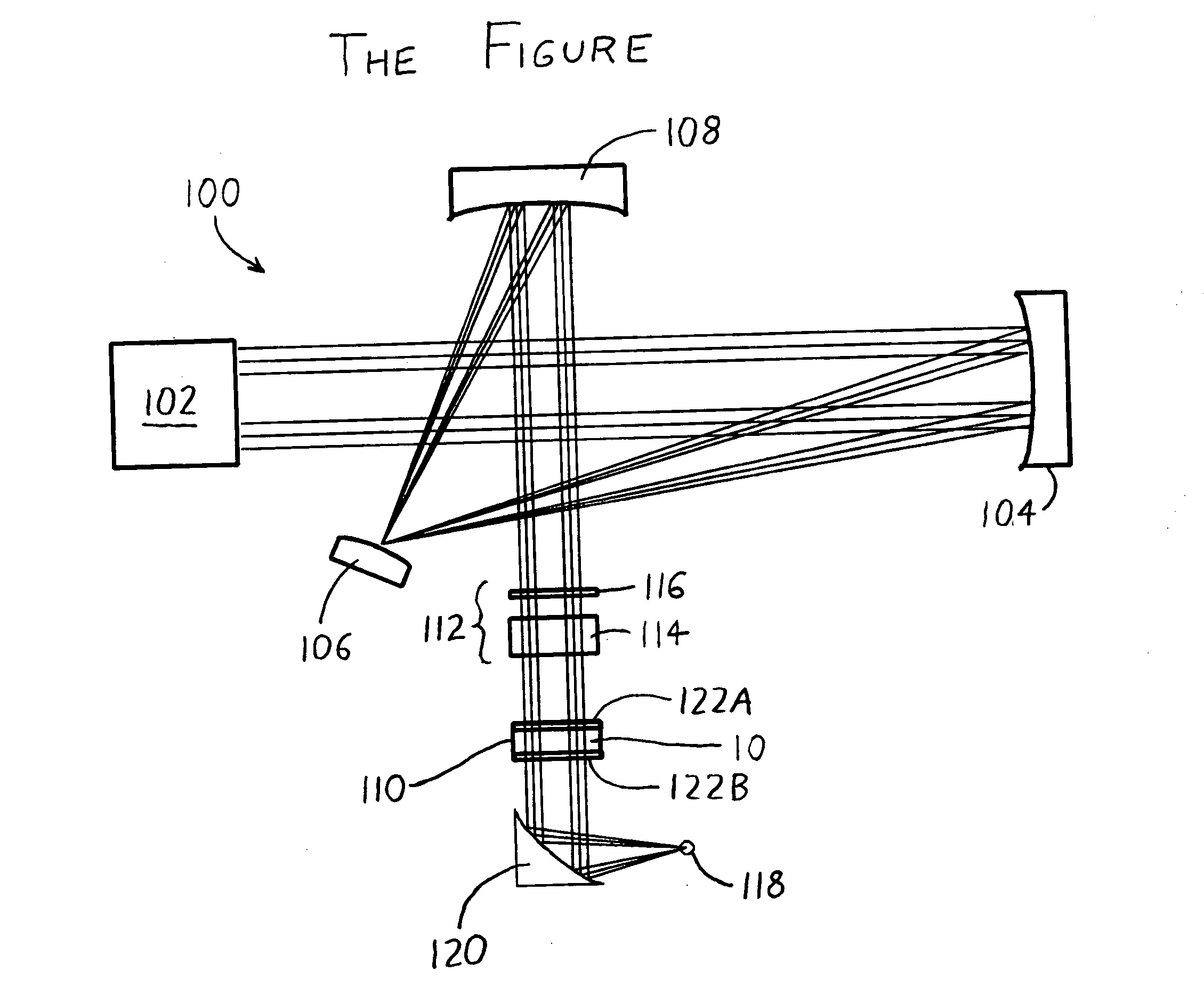
[0012]To expand on the foregoing discussion, following is a list of exemplary specific components that can be used in the foregoing arrangement. The light source 102 may be an interferometer and associated components (namely a mid-IR beamsplitter and “Passport” mirror option) taken from a Nicolet 8700 Fourier Transform Infrared (FTIR) spectrometer (Thermo Electron Corp., Waltham, Mass.). The mirrors 104, 106, and 108 can take the form of the following:

[0013]focusing mirror 104: concave spherical mirror, 500 mm radius of curvature, 50 mm diameter, preferably gold-coated.

[0014]field mirror 106: concave spherical mirror, 180 mm radius of curvature, 25 mm diameter, preferably gold-coated.

[0015]collimator 108: concave spherical mirror, 250 mm radius of curvature, 40 mm diameter, preferably gold-coated.

[0016]These can be readily custom-made by most lens manufacturers. The modulator 112 may include a Type 5-8321 wire grid IR linear polarizer 116 (Optometrics Corp, Ayer, Mass.), and a Type ...


PUM


Abstract

A spectrometer generates Vibrational Circular Dichroism (VCD) measurements having an exceedingly high signal-to-noise ratio, as well as a greater wavelength range over which measurements may be accurately provided. This is achieved by utilizing reflective optics (preferably solely reflective optics, i.e., no refractive elements) to supply a concentrated and collimated input light beam to a sample within a sample cell, and similarly collecting the light output from the sample cell via reflective optics for supply to a detector.

Description

CROSS-REFERENCE TO RELATED APPLICATIONS [0001]This application claims priority under 35 USC §119(e) to U.S. Provisional Patent Application 60 / 784,741 filed 21 Mar. 2006, the entirety of which is incorporated by reference herein.FIELD OF THE INVENTION [0002]This document concerns an invention relating generally to spectrometry, and more specifically to spectrometers for use in measurement of vibrational circular dichroism (VCD), vibrational linear dichroism (VLD), infrared reflection absorption spectroscopy (IRRAS), and other spectrometric measurements wherein the light provided to a sample to be analyzed has modulated polarization.BACKGROUND OF THE INVENTION [0003]As is well known, spectrometry is a technique wherein light is directed onto a substance to be analyzed, and the resulting light transmitted, reflected, and / or emitted by the sample is then analyzed to provide information about the substance. Vibrational circular dichroism (VCD), or VCD spectroscopy, is a spectrometric tec...

Claims


Application Information

Patent Timeline
Patent Type & Authority Applications(United States)
IPC IPC(8): G01J4/00G01J3/42
CPCG01J3/02G01N21/19G01J3/447G01J3/0208
Inventor JIANG, ERICDECK, FRANCIS J.
Owner THERMO ELECTRONICS SCI INSTR LLC
Why Eureka
Try Eureka