Spark-ignition gasoline engine

a gasoline engine and spark ignition technology, applied in the direction of machines/engines, output power, electric control, etc., can solve the problems of reducing the effective compression ratio, achieve high torque and fuel economy, reduce combustion time loss, and maintain heat generation rate. dq/d

Active Publication Date: 2007-10-04
MAZDA MOTOR CORP
View PDF5 Cites 59 Cited by
  • Summary
  • Abstract
  • Description
  • Claims
  • Application Information

AI Technical Summary

Benefits of technology

[0019]According to the present invention, even in an engine operation zone where it has been generally believed that a large amount of ignition timing retard is essentially required for preventing knock, the effective compression ratio calculated based on an intake-valve closing timing defined by a valve lift amount of 1 mm can be maintained at 13 or more to allow the engine to be operated while keeping high torque and fuel economy. Specifically, in an engine having an ignition timing retarded to a point after a compression TDC to avoid knock, a cool-flame reaction becomes prominent in cylinders after a compression TDC, and a multistage flaming phenomenon occurs in a combustion process after the compression TDC. This makes it possible to maintain a heat generation rate (dQ/dθ) while reducing a combustion time loss, so as to obtain a sufficient torque. The maintained heat generation rate also makes it possible to minimize an amount of ignition timing retard. Further, in the combustion process with the cool-flame reaction, a mol-number (i.e., the number of moles of in-cylinder gas) is increased to moderate an increase in in-cylinder temperature in spite of an increase in in-cylinder pressure. In addition, the cool-flame reaction occurs in a central region of a combustion chamber but the occurrence is less prominent in an end gas region. Thus, the increase in in-cylinder temperature is further suppressed. Under such te

Problems solved by technology

Further, the engine is designed to reduce the effective compression ratio

Method used


Image

  • Spark-ignition gasoline engine
  • Spark-ignition gasoline engine
  • Spark-ignition gasoline engine

Examples


embodiment

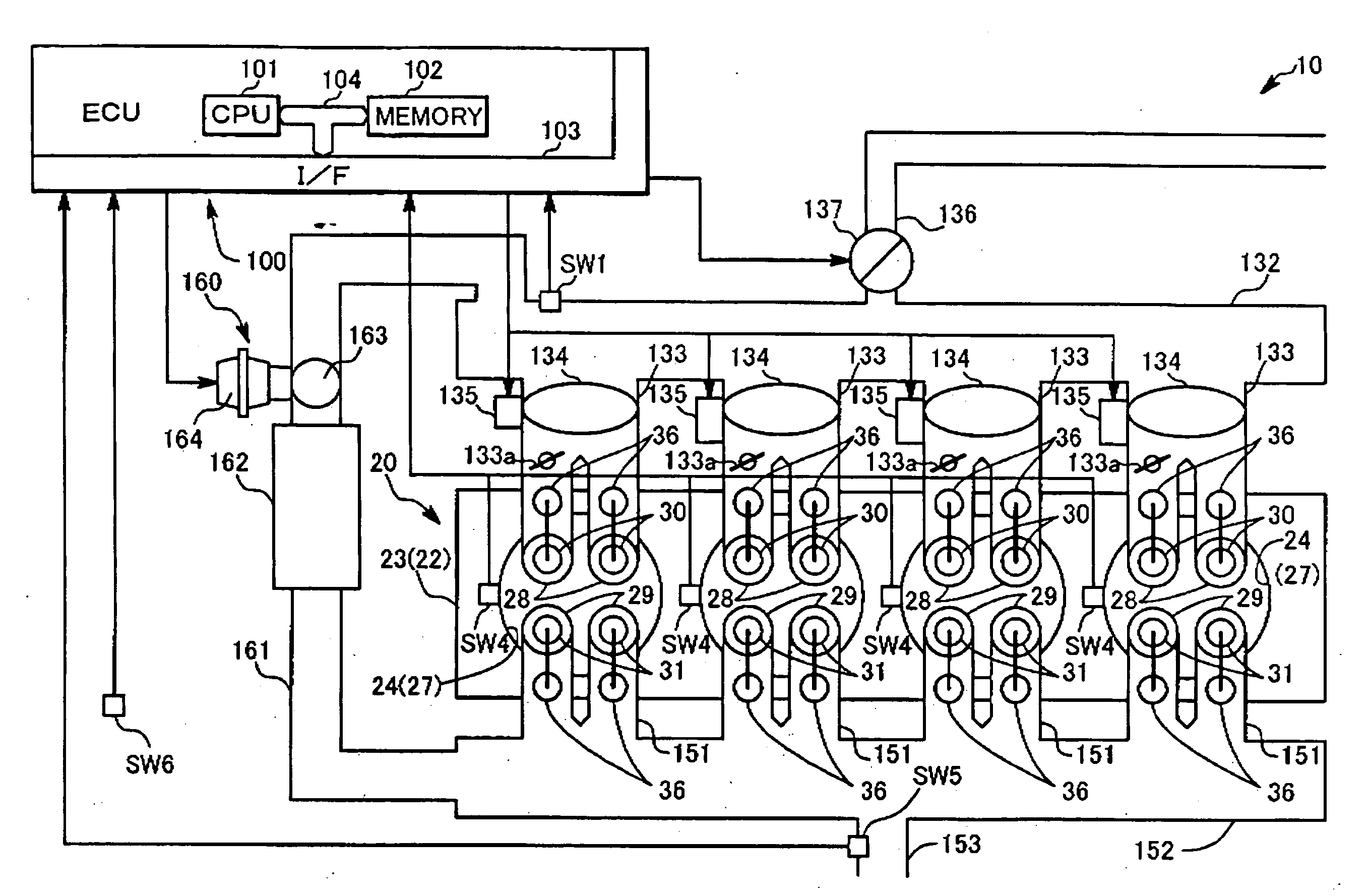
[0098]Referring to FIGS. 13 and 14, a four-stroke spark-ignition gasoline engine 10 according to one embodiment of the present invention comprises an engine body 20, and a control unit 100 for controlling various engine systems associated with the engine body 20.

[0099]The engine body 20 integrally has a cylinder block 22 rotatably supporting a crankshaft 21, and a cylinder head 23 disposed on a top surface of the cylinder block 22. The cylinder block 22 and the cylinder head 23 are designed to internally define a plurality of cylinders 24.

[0100]Each of the cylinders 24 is provided with a piston 26 connected to the crankshaft 21 through a connecting rod 25. The piston 26 defines a combustion chamber 22 in an upper region of the cylinder 24 in cooperation with the cylinder clock 22 and the cylinder head 23. In this embodiment, a geometrical compression ratio in each of the cylinders 24 is set at 14.

[0101]Referring to FIG. 14, in the engine body 20 in this embodiment, each of the cylin...


PUM


Abstract

Disclosed is a spark-ignition gasoline engine, which comprises control means operable, when an engine operation zone is a high-load operation zone including a WOT region within at least a low speed range, to adjust a closing timing of an intake valve in such a manner as to maintain an effective compression ratio at 13 or more, and retard an ignition timing to a point within a predetermined stroke range just after a top dead center of a compression stroke, wherein the effective compression ratio is calculated based on an intake-valve closing timing defined by a valve lift amount of 1 mm. The present invention can provide a spark-ignition gasoline engine having both a low-cost performance and a high engine-power performance even in a high-load operation zone (particularly WOT region) in a low speed range.

Description

BACKGROUND OF THE INVENTION[0001]1. Field of the Invention[0002]The present invention relates to a spark-ignition gasoline engine.[0003]2. Description of the Related Art[0004]A spark-ignition gasoline engine is regarded as following an Otto Cycle in theory, wherein its theoretical thermal efficiency ηth is expressed by the following Formula, as disclosed, for example, in “Internal Combustion Engine Fundamentals” (Document D1) authored by John B. Heywood:ηth=1−(1 / εk−1)  (1)[0005]wherein ε is a compression ratio, and κ is a specific heat ratio.[0006]As is clear from Formula (1), the theoretical thermal efficiency (i.e., indicated, net thermal efficiency) of the spark-ignition gasoline engine is improved up to a certain level as the compression ratio is set at a higher value. In this relation, the Document D1 reports a research on changes in theoretical thermal efficiency at various compression ratios (8≦ε≦20) under the conditions that a spark-ignition gasoline engine is operated at wi...

Claims


Application Information

Patent Timeline
IPC IPC(8): F02P5/00F02B75/02
CPCF02D13/0223F02D13/0269F02D15/04F02D37/02F02D41/0002Y02T10/42F02P5/151F02P5/1512Y02T10/46Y02T10/142F02D2041/001F02D41/3029F02D41/402Y02T10/12Y02T10/40
Inventor HITOMI, MITSUOIWATA, NORIYUKIYAMAKAWA, MASAHISANISHIMOTO, TOSHIAKIYOHSO, TAKASHIHAYASHI, TAKAYOSHI
Owner MAZDA MOTOR CORP
Why Eureka
Try Eureka