
Plasma processing apparatus

a processing apparatus and plasma technology, applied in the direction of electrical apparatus, basic electric elements, electric discharge tubes, etc., can solve the problems of deterioration of the uniformity of the electric field intensity distribution, increase of power consumption, and non-radial uniformity of the processing characteristics, so as to improve the efficiency and accuracy of the plasma processing

Active Publication Date: 2007-10-04
TOKYO ELECTRON LTD
View PDF11 Cites 23 Cited by
  • Summary
  • Abstract
  • Description
  • Claims
  • Application Information

AI Technical Summary

Benefits of technology

[0009]In particular, the present invention provides a plasma processing apparatus capable of improving efficiency and accuracy of a plasma processing by independently controlling electric field intensity distributions of respective high frequency powers for plasma generation and for ion attraction in a type in which dual frequency powers are applied to a lower electrode.
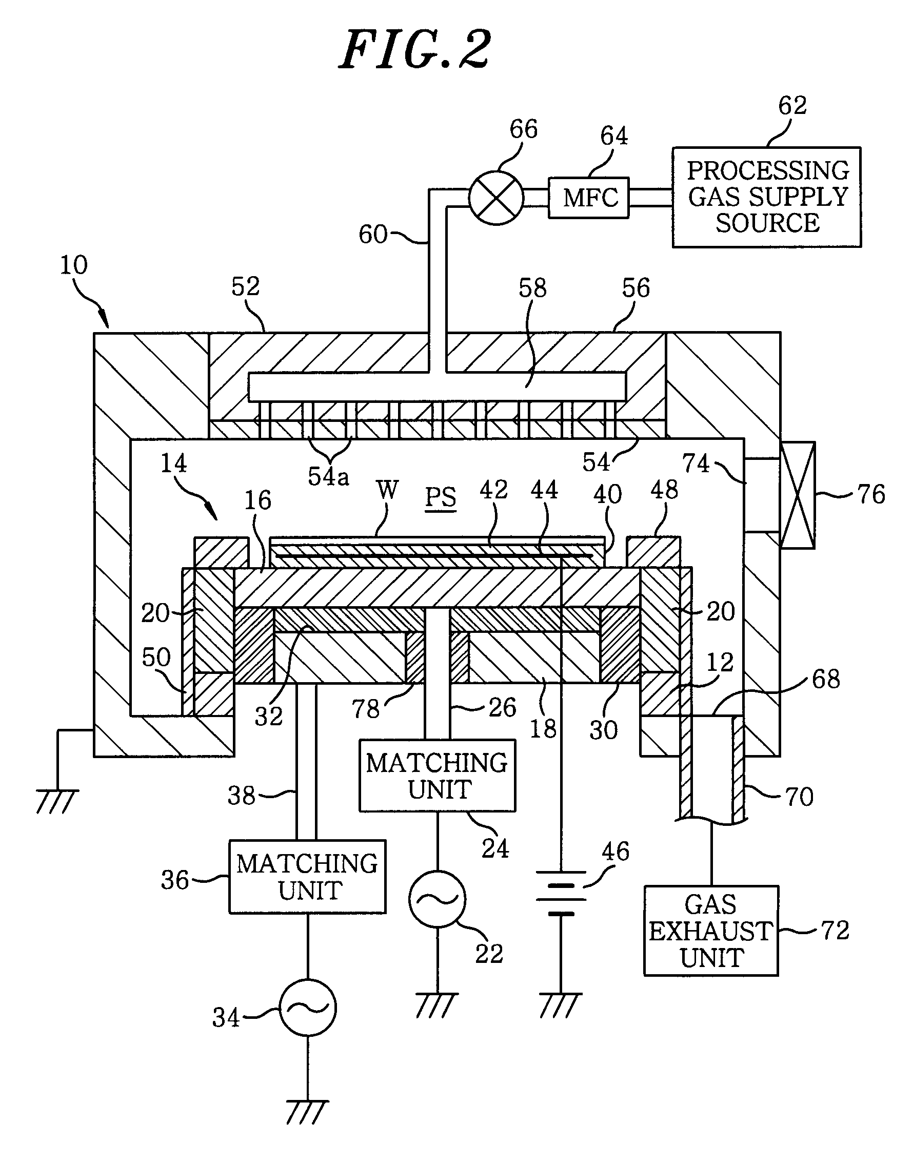
[0013]Typically, in a case where a high frequency is discharged into the plasma space from the second lower electrode, a magnetic field generated by a vortex current flowing in the first lower electrode functions to prevent a straight movement of the high frequency from the second lower electrode. To that end, in order to suppress the vortex current in the first lower electrode, the first lower electrode is preferably formed with a high-resistivity material. Further, since the first high frequency power functioning to attract ions to the substrate to be processed has a relatively low frequency, the skin effect in the first lower electrode becomes small. Accordingly, there is not required a special electrode structure for the first lower electrode and, typically, a flat plate electrode made of a single material to have a constant thickness can be used as the first lower electrode.
[0016]In accordance with the present invention, as described above, in a capacitively coupled plasma processing apparatus of a type in which two high frequency powers of different frequencies are applied to one of electrodes (particularly, a lower electrode), the electrode is vertically divided into two and the high frequency powers are individually applied to the respective divided electrodes. Accordingly, functions or actions of dual high frequency powers can be concurrently optimized. Particularly, in a type in which dual frequency powers are applied to a lower electrode, it is possible to improve efficiency and accuracy of a plasma processing by independently controlling electric field intensity distributions of respective high frequency powers for plasma generation and for ion attraction.

Problems solved by technology

As a result, there occurs a problem that process characteristics become nonuniform in a radial direction.
Further, there has been also proposed an electrode structure with a high-resistance member disposed at a central portion of the electrode, but this structure results in an increase of power consumption due to a Joule heat (see, for example, Japanese Patent Laid-open Publication No. 2000-323456 and U.S. Patent Application Publication No. 2005-61445).
However, for the high frequency power of the low frequency for ion attraction, an electric field intensity at the central portion of the lower electrode becomes lower than that at the edge portion thereof, which results in a deterioration of the uniformity of the electric field intensity distribution.
Thus, there is a trade-off problem that a uniformity of anisotropic etching accuracy is deteriorated while the uniformity of the plasma density can be improved.

Method used


Image

  • Plasma processing apparatus
  • Plasma processing apparatus
  • Plasma processing apparatus

Examples


first embodiment

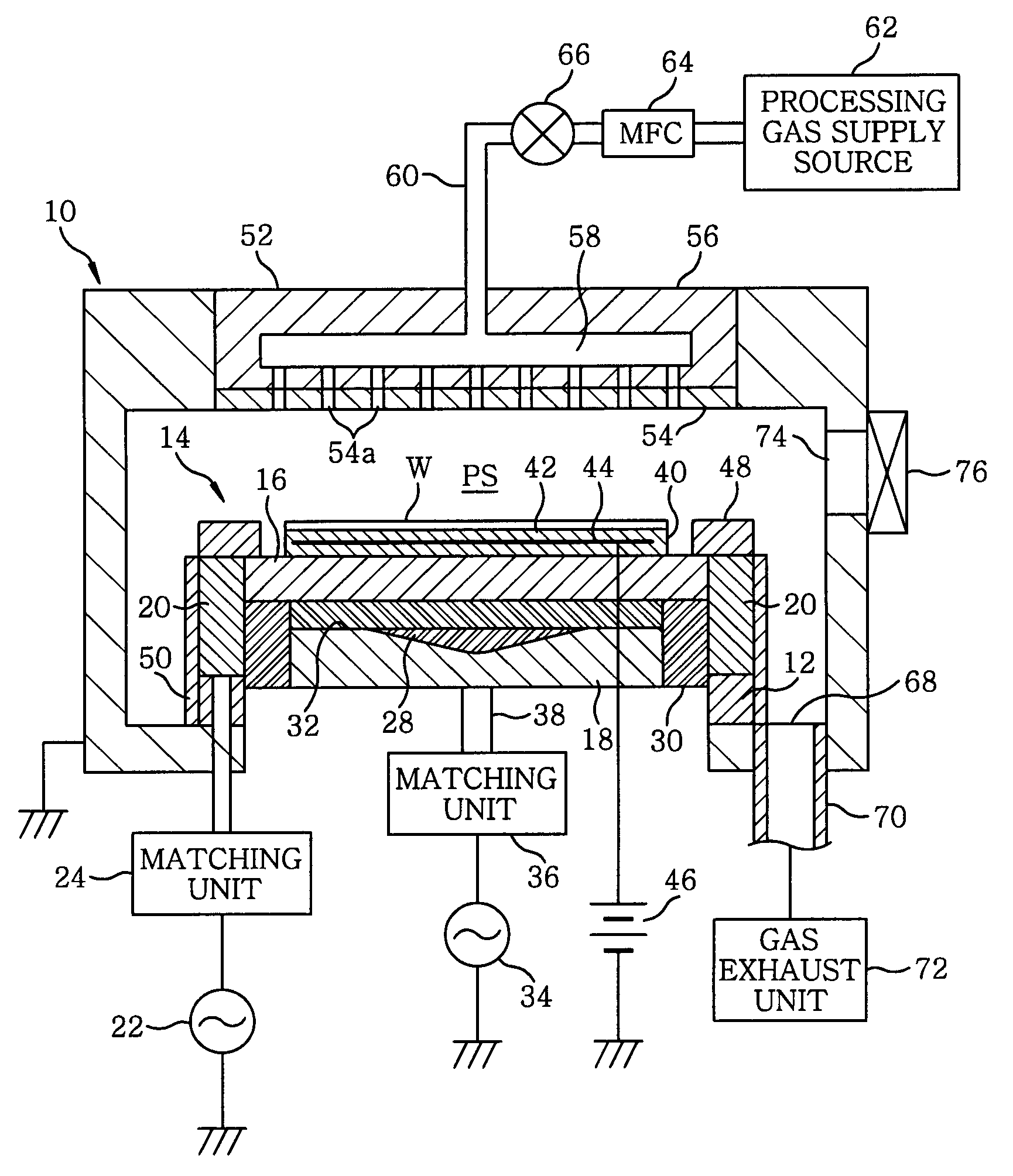
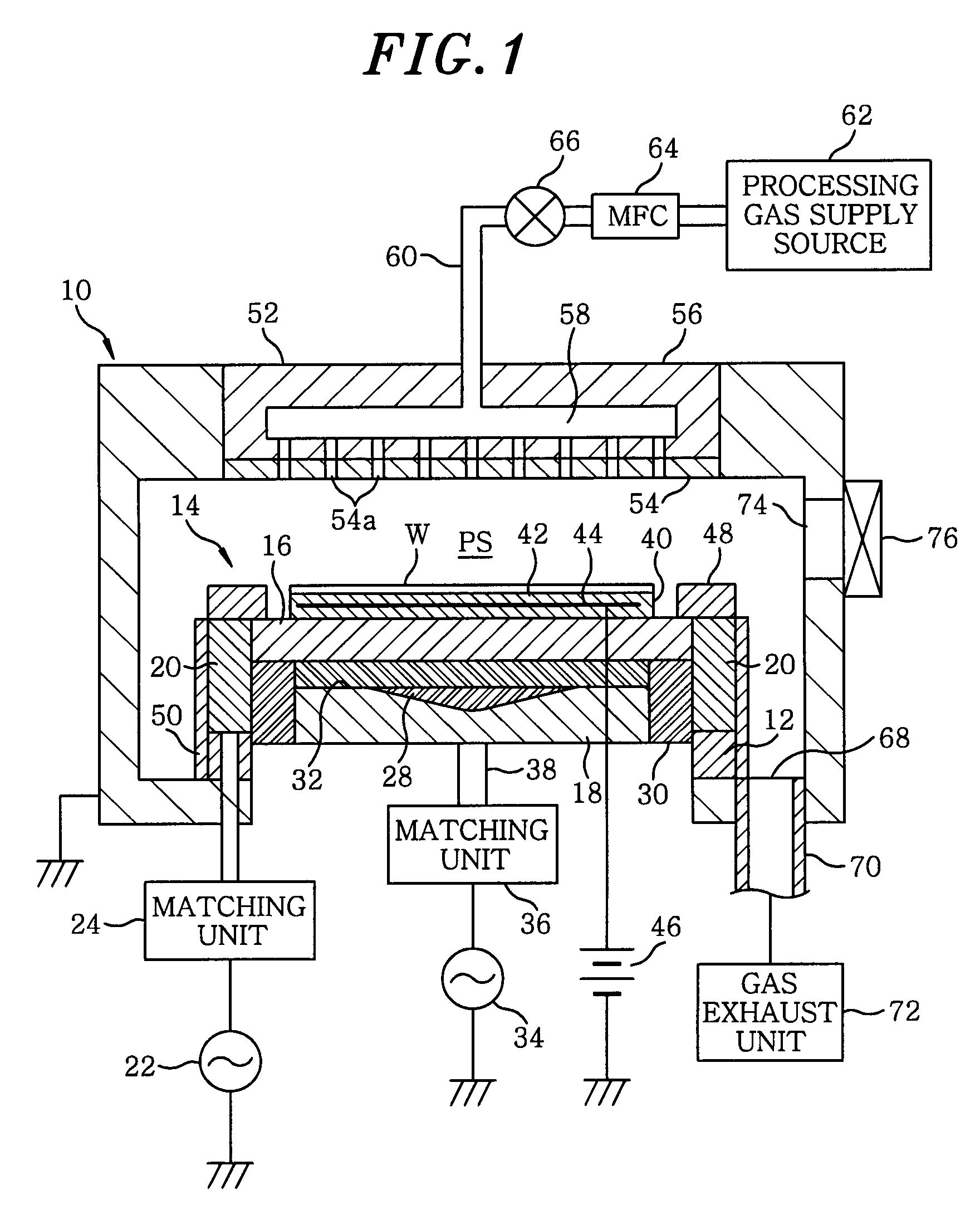
[0022]FIG. 1 illustrates a configuration of a plasma etching apparatus in accordance with the present invention. The plasma etching apparatus is configured as a capacitively coupled plasma processing apparatus of a type that applies dual frequency powers to a lower electrode. The plasma etching apparatus has a cylindrical chamber (processing chamber) 10 made of a metal such as aluminum or stainless steel, and the chamber 10 is frame grounded.

[0023]A susceptor 14 serving as a lower electrode and a substrate supporting table is disposed at a bottom portion in the chamber 10 via an annular insulating member 12 made of, e.g., ceramic. The susceptor 14 has an upper susceptor electrode 16 and a lower susceptor electrode 18 serving as a first and a second lower electrode, respectively.

[0024]On the annular insulating member 12, there is provided an annular or a cylindrical power feeder 20, and the upper susceptor electrode 16 is attached to the upper portion of the power feeder 20 substanti...

second embodiment

[0042]Moreover, the present invention can also be applied to a plasma processing apparatus of a type in which a high frequency power applied to an upper electrode side. For example, in the present invention shown in FIG. 3, the present invention is applied to an upper electrode 80 of a capacitively coupled plasma etching apparatus wherein powers of different high frequencies are respectively applied to the upper electrode 80 and a susceptor (lower electrode) 82. The upper electrode 80 includes a first upper electrode 84 disposed to face down the susceptor 82 with a plasma space PS present therebetween; and a second upper electrode 86 disposed at a rear side of the first upper electrode 84 when viewed from the plasma space PS or above the first upper electrode 84.

[0043]More specifically, the first upper electrode 84 has an electrode structure also serving as a shower head, and it is connected to a processing chamber 90 in a floating state, are electrically isolated from the chamber 9...


PUM

PropertyMeasurementUnit
frequencyaaaaaaaaaa
frequencyaaaaaaaaaa
frequencyaaaaaaaaaa

Abstract

In a plasma processing apparatus including a vacuum-evacuable processing chamber, a first lower electrode for supporting a substrate to be processed thereon is disposed in the processing chamber and an upper electrode is disposed above the first lower electrode to face the first lower electrode. Further, a second lower electrode is disposed under the first lower electrode while being electrically isolated from the first lower electrode. A processing gas supply unit supplies a processing gas into a space between the upper electrode and the first lower electrode. A first high frequency power supply unit applies a first high frequency power of a first frequency to the first lower electrode, and a second high frequency power supply unit applies a second high frequency power of a second frequency higher than the first frequency to the second lower electrode.

Description

FIELD OF THE INVENTION [0001]The present invention relates to a technique for performing a plasma etching on a substrate to be processed; and, more particularly, to a capacitively coupled plasma processing apparatus of a type in which dual high frequency powers of different frequencies are applied to an electrode.BACKGROUND OF THE INVENTION [0002]In a manufacturing process of semiconductor devices or flat panel displays (FPDs), a plasma is used to perform a micro-processing, such as etching, deposition, oxidation, sputtering or the like, so as to obtain a good reaction of a processing gas at a relatively low temperature. Conventionally, a capacitively coupled type plasma apparatus has been widely employed as a single-wafer plasma processing apparatus, especially, as a single-wafer plasma etching apparatus.[0003]Generally, in the capacitively coupled plasma processing apparatus, an upper electrode and a lower electrode are disposed to face each other in parallel in a vacuum processin...

Claims


Application Information

Patent Timeline
Patent Type & Authority Applications(United States)
IPC IPC(8): C23F1/00
CPCH01J37/32165H01J37/32082
Inventor YAMAZAWA, YOHEI
Owner TOKYO ELECTRON LTD
Learn More