Thin-film transistor formed on insulating substrate
a thin film transistor and substrate technology, applied in the direction of transistors, semiconductor devices, electrical devices, etc., can solve the problems of non-uniform device characteristics, reduced non-uniform probability of grain boundary presence, etc., to achieve reduced possibility of device destruction, high-speed operation, and reduced non-uniform device characteristics
- Summary
- Abstract
- Description
- Claims
- Application Information
AI Technical Summary
Benefits of technology
Problems solved by technology
Method used
Image
Examples
first embodiment
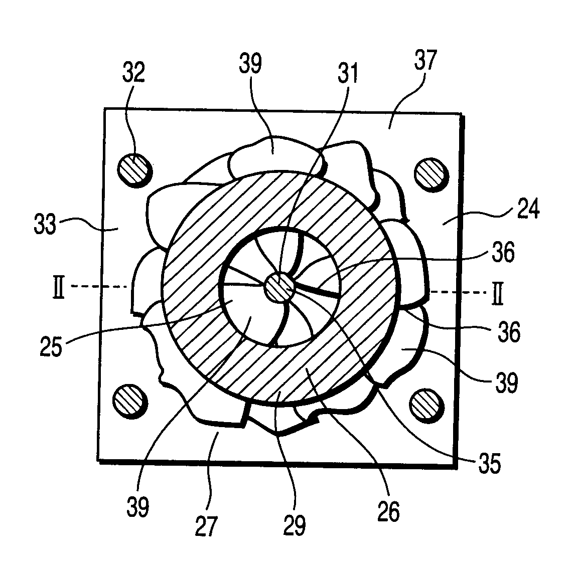
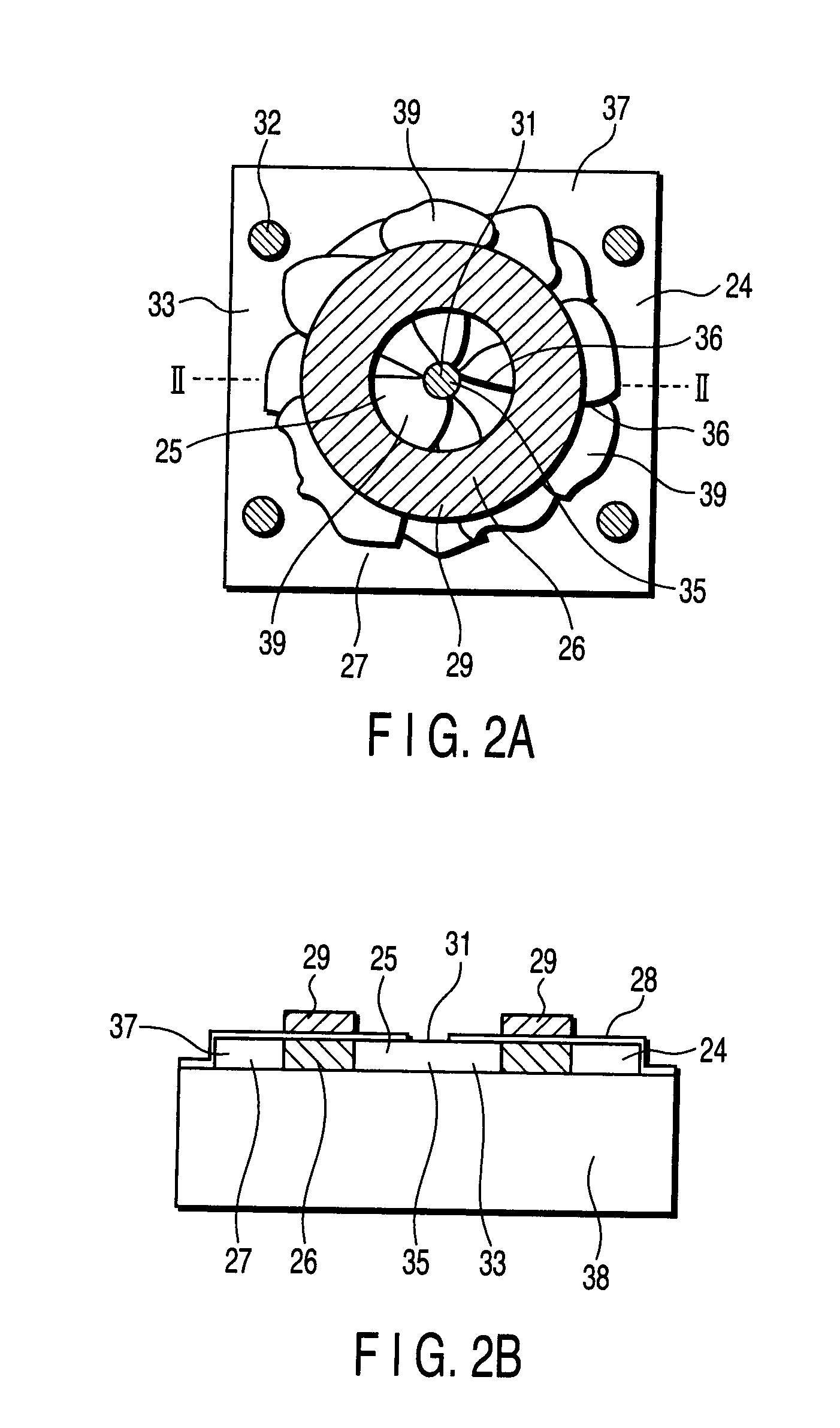
[0051]FIG. 2A and FIG. 2B show an example of the structure of a thin-film transistor according to a first embodiment of the present invention. FIG. 2A is a plan view and FIG. 2B is a cross-sectional view taken along line II-II in FIG. 2A.
[0052] As is shown in FIG. 2A and FIG. 2B, the thin-film transistor according to the first embodiment of the invention is formed on a semiconductor island 33 that is formed of a thin-film semiconductor 24 with a thickness of, e.g. 100 nm thick on an insulating substrate 38. A glass substrate, for instance, is used as the insulating substrate 38. In particular, it is preferable that a no-alkali glass substrate be used as the insulating substrate 38. It is also possible to use a quartz substrate or a plastic substrate, depending on necessity. For electrical isolation between neighboring devices, each thin-film semiconductor 24 is formed as a square thin-film semiconductor island 33 with a dimension of, e.g. 15 μm on each side. The shape of the semico...
second embodiment
[0079]FIG. 9A is a plan view that shows the structure of a second embodiment of the invention, and FIG. 9B is a cross-sectional view taken along line IX-IX in FIG. 9A. Like the structure shown in FIG. 2A, a semiconductor island 69 on an insulating substrate 71 is provided with a source region 61, a channel region 62, a drain region 63, a gate insulation film 64, a gate electrode 65, a source contact hole 66 and drain contact holes 68.
[0080] In the thin-film transistor shown in FIG. 2A, the channel region is doped with phosphorus (in the case of a PMOS transistor) or boron (in the case of an NMOS transistor) with a concentration of 1016 / cm3 to 1017 / cm3. In the second embodiment, an offset region 70, which has the same impurity concentration as the channel region, is provided between the drain region 63 and the channel region 62. The presence of the offset region 70 facilitates extension of a depletion layer in this region, and thus an increase in electric field at the end of the dra...
third embodiment
[0081]FIG. 10A is a plan view that shows the structure of a third embodiment of the invention, and FIG. 10B is a cross-sectional view taken along line X-X in FIG. 10A.
[0082] Like the structure shown in FIG. 9A, a semiconductor island 69 on an insulating substrate 71 is provided with a source region 61, a channel region 62, a drain region 63, a gate insulation film 64, a gate electrode 65, a source contact hole 66 and drain contact holes 68.
[0083] The thin-film transistor shown in FIG. 10A differs from the thin-film transistor shown in FIG. 2A in that an LDD (lightly doped drain) region 73 is provided between the drain region 63 and the channel region 62. The LDD region 73 is doped with impurities with a concentration that is lower than the concentration in the drain region 63 and is higher than the concentration in the channel region 62. The LDD region 73 is doped with the same kind of impurities as in the drain region with a concentration of 1018 / cm3. The presence of the LDD regi...
PUM
 Abstract
Description
Claims
Application Information
 - R&D
- Intellectual Property
- Life Sciences
- Materials
- Tech Scout
- Unparalleled Data Quality
- Higher Quality Content
- 60% Fewer Hallucinations
Browse by: Latest US Patents, China's latest patents, Technical Efficacy Thesaurus, Application Domain, Technology Topic, Popular Technical Reports.
© 2025 PatSnap. All rights reserved.Legal|Privacy policy|Modern Slavery Act Transparency Statement|Sitemap|About US| Contact US: help@patsnap.com


