High speed signal transmission structure

a transmission structure and signal technology, applied in the field of transmission techniques of electrical signals, can solve the problems of unwanted coupling between conductors in a circuit, adversely affecting the performance of the circuit, digital system failure, etc., and achieve the effects of reducing the switching rate of signals, reducing or even eliminating the problems of crosstalk, overshooting and undershooting, and simple manufacturing

Inactive Publication Date: 2007-10-04
HONG FU JIN PRECISION IND (SHENZHEN) CO LTD +1
View PDF2 Cites 127 Cited by
  • Summary
  • Abstract
  • Description
  • Claims
  • Application Information

AI Technical Summary

Benefits of technology

[0010]The copper patch serves as a compensation capacitor, to reduce a rate of switching of signals, and to reduce or even eliminate the problems of crosst

Problems solved by technology

It is important as the mechanism by which transformers work, but it can also cause unwanted coupling between conductors in a circuit.
Crosstalk can cause digital system failure due to false signals appearing on a receiver.
However, in some circuits, the fast signal rise time can cause reflections and/or electrom

Method used


Image

  • High speed signal transmission structure
  • High speed signal transmission structure
  • High speed signal transmission structure

Examples


Embodiment Construction

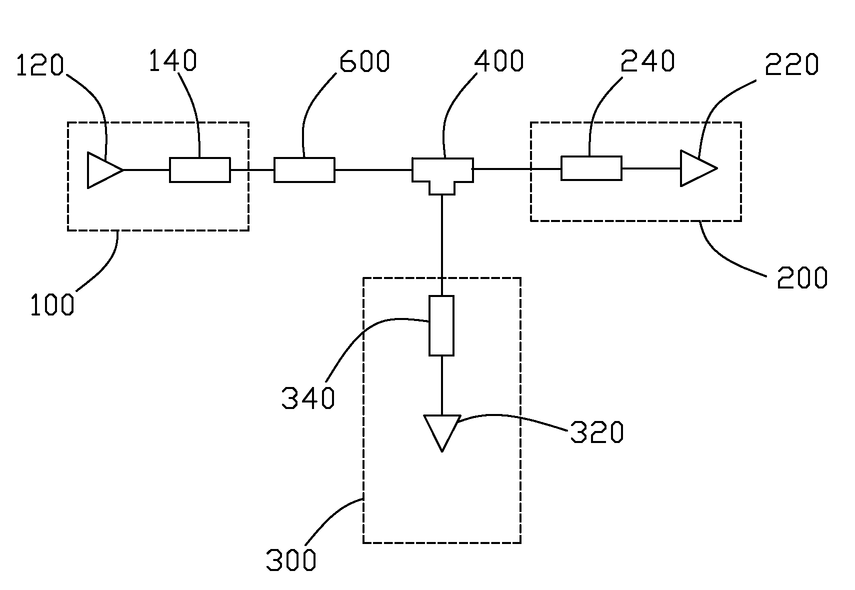
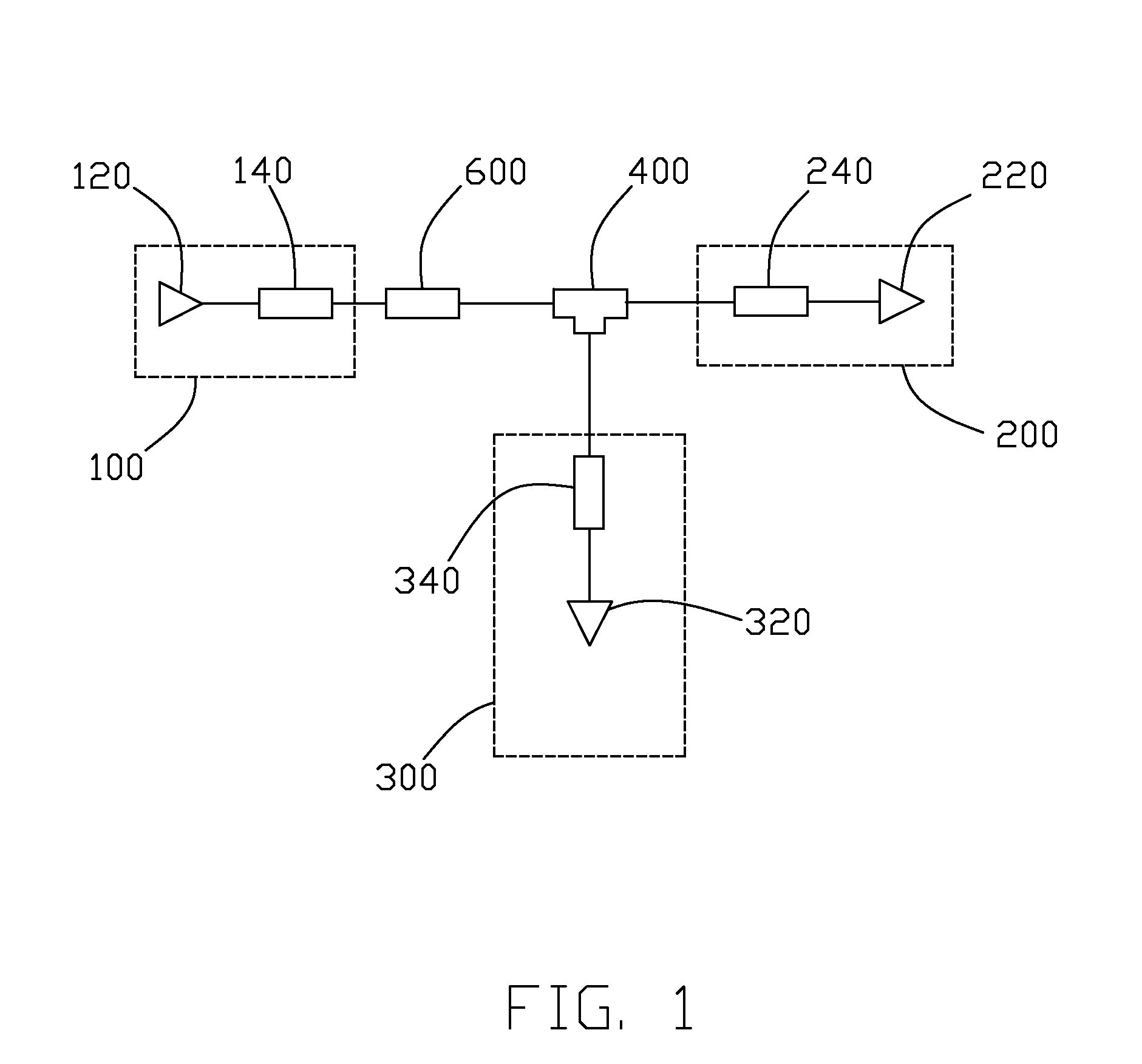
[0017]Referring to FIG. 1, a signal transmission structure in accordance with a preferred embodiment of the present invention includes a driving circuit block 100, a first receiving circuit block 200, and a second receiving circuit block 300. A main transmission line 400 connects to the driving circuit block 100, the first receiving circuit block 200, and the second receiving circuit block 300. The driving circuit block 100 includes a driving circuit 120 and a branch transmission line 140. The first receiving circuit block 200 includes a first receiving circuit 220, and a branch transmission line 240. The second receiving circuit block 300 includes a second receiving circuit 320, and a branch transmission line 340. The main transmission line 400 serves a main transmission function, and the branch transmission lines 140, 240, 340 serve signal transmission functions within circuit blocks 100, 200, 300 respectively. A copper patch 600 having a generally rectangular shape is located at ...


PUM


Abstract

A signal transmission structure includes a driving circuit block, a receiving circuit block, a main transmission line, and a copper patch. The main transmission line connects the driving circuit block to the receiving circuit block for transmitting signals therebetween. The copper patch is arranged at the main transmission line, and has a rectangular shape. The copper patch can reduce switching rates when the signal state of the driving circuit changes rapidly. The copper patch serves as a compensation capacitor, to reduce a rate of switching of the signal, and to reduce or even eliminate the problems of crosstalk and overshooting and undershooting of signals. It is of advantage that the copper patch is simple to manufacture and very suitable for mass production.

Description

BACKGROUND OF THE INVENTION[0001]1. Field of the Invention[0002]The present invention relates to techniques of transmitting electrical signals, and particularly to a high speed signal transmission structure that can maintain signal integrity.[0003]2. Description of Related Art[0004]Mutual capacitance is the coupling of two electric fields, where electrical current proportional to the rate of change of voltage in a driver flows into a target line. The shorter the distance between two electrically conductive objects, the greater their mutual capacitance. Mutual inductance is the concept that the current through one inductor can induce a voltage in another nearby inductor. It is important as the mechanism by which transformers work, but it can also cause unwanted coupling between conductors in a circuit.[0005]Crosstalk is the electrical “noise” caused by mutual inductance and mutual capacitance between signal conductors in close proximity to each other. Crosstalk can cause digital syst...

Claims


Application Information

Patent Timeline
IPC IPC(8): H01P5/12
CPCH01P3/08H05K2201/09727H05K1/162H05K1/025
Inventor LIU, NINGLIN, YU-HSUMENG, YUN-QIANG
Owner HONG FU JIN PRECISION IND (SHENZHEN) CO LTD
Why Eureka
Try Eureka