Fiber laser oscillator and fiber laser processing apparatus

a technology of fiber laser and processing apparatus, which is applied in the direction of optical elements, manufacturing tools, instruments, etc., can solve the problems of easy burnout of the end surface of the oscillation fiber, and easy burnout of the end surface of the core by the energy of the incident light, so as to improve the stability of laser power, and prevent burnout or deterioration of an active medium

Inactive Publication Date: 2007-10-04
MIYACHI TECHNOS CORP
View PDF0 Cites 14 Cited by
  • Summary
  • Abstract
  • Description
  • Claims
  • Application Information

AI Technical Summary

Benefits of technology

[0017] The fiber laser oscillator of the present invention can prevent burnout or deterioration of an active medium to improve stability of laser power with the above configurations and effects. The fiber laser processing apparatus of the present invention can prevent burnout or deterioration of an active medium to achieve stability of laser power and to improve credibility of a laser process with the above configurations and effects.

Problems solved by technology

With regard to the drawbacks of the fiber laser oscillator, it is problematic that the end surface of the oscillation fiber easily burns out.
Therefore, since the base material of the core, i.e., quartz glass has a damage threshold lower than crystals such as YAG, the end surface of the core tends to be burned by the energy of the incident light.
Therefore, the laser oscillation in the optical oscillator itself causes burnout of the core end surface.
If the core end surface of the oscillation optical fiber is burned out, the oscillation power of the fiber laser is reduced and the quality of the laser process is deteriorated.

Method used


Image

  • Fiber laser oscillator and fiber laser processing apparatus
  • Fiber laser oscillator and fiber laser processing apparatus
  • Fiber laser oscillator and fiber laser processing apparatus

Examples


Embodiment Construction

[0025] Preferred embodiments of the present invention will hereinafter be described with reference to the accompanying drawings.

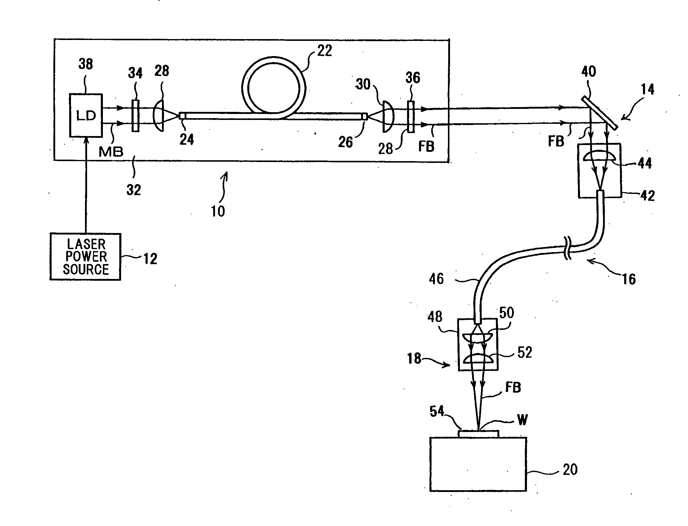
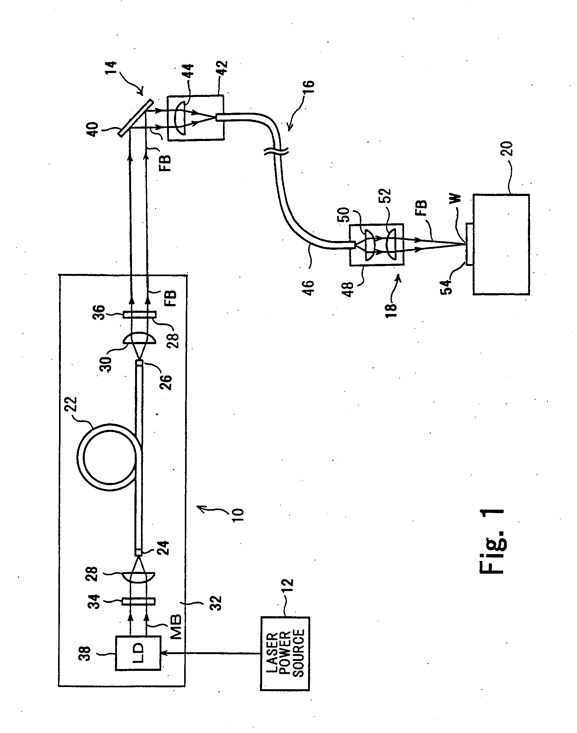
[0026]FIG. 1 depicts a configuration of a fiber laser processing apparatus according to one embodiment of the present invention. This fiber laser processing apparatus is configured by a fiber laser oscillator 10, a laser power source 12, a laser incident unit 14, a fiber transmission system 16, a laser emitting unit 18, a processing table 20, etc.

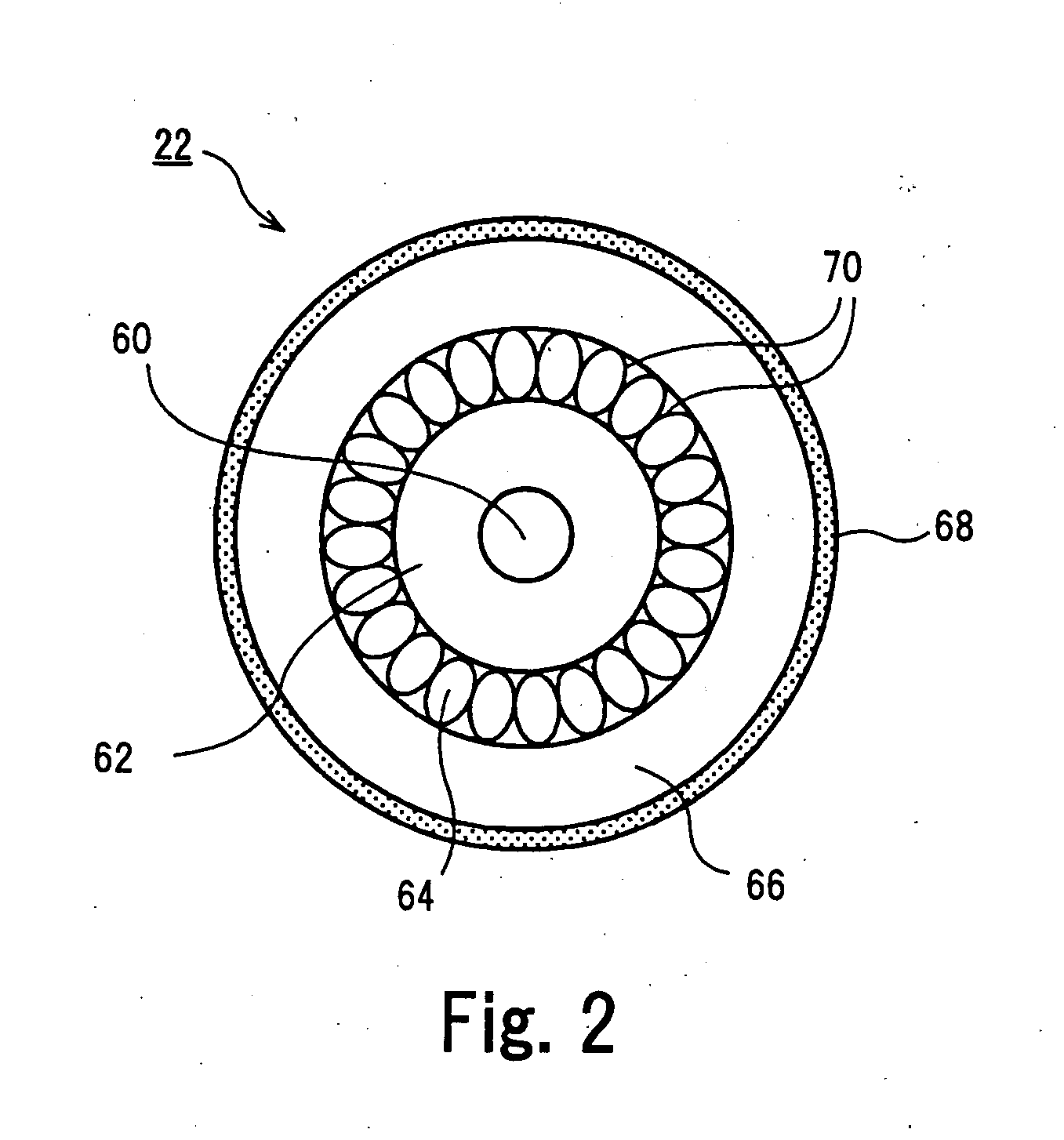
[0027] The fiber laser oscillator 10 includes an optical fiber for oscillation (hereinafter, “oscillation fiber”) 22, a pair of end caps 24 and 26 bonded to both end surfaces of the oscillation fiber 22, optical lenses 28 and 30 located at a focal distance from the both ends of the oscillation fiber 22, an electro-optic exciting unit 32 that applies pumping excitation light MB to one end surface of the oscillation fiber 22, and a pair of optically opposing optical resonator mirrors 34 and 36.

[0028] The electro-o...


PUM

PropertyMeasurementUnit
diameteraaaaaaaaaa
lengthaaaaaaaaaa
optically transparentaaaaaaaaaa

Abstract

An end cap is formed as a substantially cylindrical body having substantially the same diameter as an external diameter of a retaining unit of an oscillation fiber; a base end surface is integrally fusion-welded or fusion-bonded to one end surface of the oscillation fiber; and a leading end surface is obliquely cut relative to the light axis. A returning oscillating beam reflected by an optical resonator mirror is converged and made incident on a core end surface of the oscillation fiber 22 located at a focus position of an optical lens. However, since the core end surface is integrally bonded with the end cap and is not exposed to the atmosphere, the core end surface is not burned or deteriorated by the light energy of the oscillating beam.

Description

BACKGROUND OF THE INVENTION [0001] 1. Field of the Invention [0002] The present invention relates to a fiber laser oscillator that uses an optical fiber to oscillate and output a laser beam and a laser processing apparatus that applies a laser beam to a workpiece to perform a desired laser process. [0003] 2. Description of the Related Art [0004] Recently, a fiber laser processing apparatus is coming into practical use, which applies a laser beam generated by a fiber laser oscillator to a workpiece to perform a desired laser process. [0005] Generally, in a fiber laser oscillator used in a fiber laser processing apparatus, an optical fiber for oscillation having a core doped with a rare-earth element is optically disposed between a pair of optical oscillator mirrors; the core of the optical fiber is optically excited; an oscillating beam with a predetermined wavelength axially comes out from an end surface of the core and is reciprocated many times between the optical oscillator mirro...

Claims


Application Information

Patent Timeline
Patent Type & Authority Applications(United States)
IPC IPC(8): H01S3/30
CPCB23K26/0639B23K26/0643B23K26/0648B23K26/0665H01S3/094003G02B6/262G02B6/4296H01S3/067H01S3/06708G02B6/02366B23K26/064G02B6/00G02B6/32
Inventor MATSUDA, YASUSHISHIMADA, HIDENORI
Owner MIYACHI TECHNOS CORP
Why Eureka
Try Eureka