SELECTIVE CATALYTIC REDUCTION OF NOx ENABLED BY UREA DECOMPOSITION IN HEAT-EXCHANGER BYPASS

a technology of nox and heat exchanger, applied in the field ofnox, can solve the problems of urea safety, high temperature, and inability to enable the use of lower temperatures

Inactive Publication Date: 2007-10-04
FUEL TECH
View PDF2 Cites 46 Cited by
  • Summary
  • Abstract
  • Description
  • Claims
  • Application Information

AI Technical Summary

Benefits of technology

[0011] The invention provides a practical way to achieve sufficiently uniform mixing of active gaseous reactants for NOx reduction by SCR using aqueous urea as the reagent and novel process arrangements that assure that the gases are at the proper temperature for effective NOx reduction.

Problems solved by technology

Again the temperatures are high, and the use of lower temperatures is not enabled.
Urea is safer, but has not been practical for many SCR applications due to the difficulty in converting it from a solid or an aqueous form to its active gaseous species that are reactive on catalyst bed for NOx reduction.
Under low load conditions, the combustion gases are often cooled to temperatures so low that an aqueous solution of urea cannot be fully vaporized with the release of its active gaseous species.
The use of catalysts for NOx reduction utilizing urea is effective but is sensitive to particulates and undecomposed urea, which can foul a catalyst.
In this regard, it must be remembered that temperatures at the low end of the SCR treatment temperature range will not be high enough to fully gasify the urea.
In addition, SCR requires very uniform mixing of active gaseous species prior to contact with the catalyst, and it is difficult to uniformly mix urea or its decomposition products with the large amounts of effluent in need of treatment.
Regardless of physical form, urea takes time to break down in hot exhaust gases and may cause nozzle plugging at the temperatures most conducive to gasification.
This disclosure highlights the problems making it a necessity that the urea solution is maintained at a temperature below 100° C. to prevent hydrolysis in the injection equipment, and they also use dilute solutions to avoid hydrolysis in the equipment and this adds to the need for heat to evaporate the water.

Method used


Image

  • SELECTIVE CATALYTIC REDUCTION OF NOx ENABLED BY UREA DECOMPOSITION IN HEAT-EXCHANGER BYPASS
  • SELECTIVE CATALYTIC REDUCTION OF NOx ENABLED BY UREA DECOMPOSITION IN HEAT-EXCHANGER BYPASS
  • SELECTIVE CATALYTIC REDUCTION OF NOx ENABLED BY UREA DECOMPOSITION IN HEAT-EXCHANGER BYPASS

Examples


Embodiment Construction

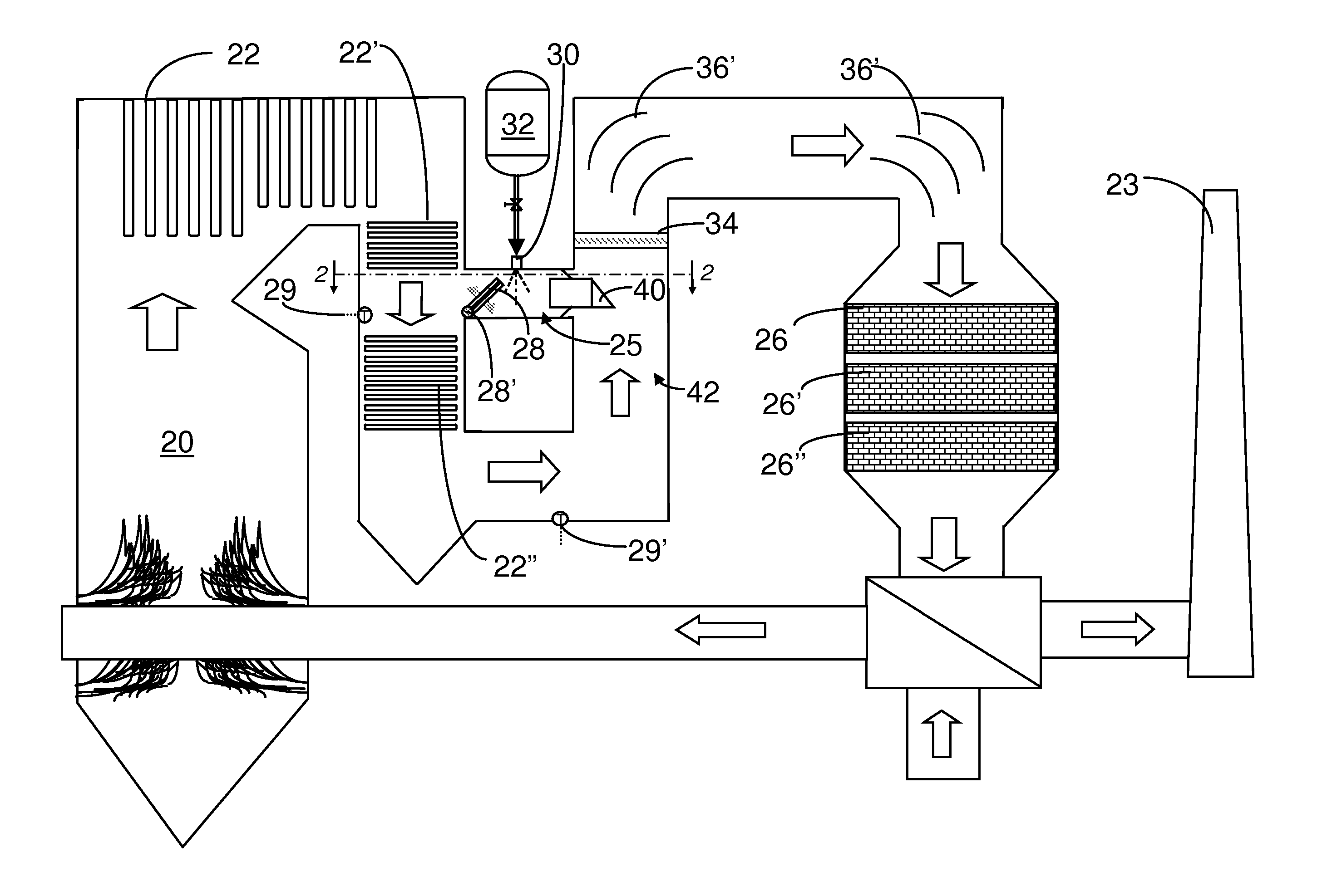
[0021] The invention provides a urea-based SCR process that can advantageously utilize the enthalpy of the flue gas, which can be supplemented if need be, to convert urea to ammonia.

[0022] This new process makes use of the easy handling feature of urea reagent and provides complete gasification and good mixing employing a bypass stream gas mass to provide thorough mixing required for high levels of NOx reduction. In particularly advantageous embodiments, heat necessary for gasification is derived solely from the enthalpy of the combustion gases.

[0023] The process is effective with urea, but can utilize other NOx-reducing reagents capable of generating a reactant gas containing ammonia upon heating. As will be clear from the following, when certain of these reagents are gasified, the reactant gas will also contain HNCO which can react with water from combustion and the aqueous reagent solution to convert to ammonia and carbon dioxide. It is an advantage of the invention that this c...


PUM

PropertyMeasurementUnit
temperatureaaaaaaaaaa
temperaturesaaaaaaaaaa

Abstract

Disclosed are a process and apparatus for selective catalytic reduction of NOx. The process is enabled by passing a heat exchanger section, such as an economizer, of the boiler in advance of an SCR unit at low load conditions to enable NOx reduction even at low loads using urea instead of ammonia. In a preferred form, under high load conditions, the bypass can be almost fully closed and the economizer can be operated normally without excessively cooling the combustion gases, using only a portion of bypassed gases which are hot enough to decompose the urea into its active components including ammonia.

Description

RELATED APPLICATION [0001] This application claims priority to prior U.S. patent application Ser. No. 11 / 275,989 filed Feb. 8, 2006, which is a divisional of U.S. patent application Ser. No. 10 / 031,724 filed Dec. 3, 2001, which are incorporated herein by reference in their entireties.BACKGROUND OF INVENTION [0002] The invention permits NOx reduction using urea instead of ammonia, even at low loads. The invention provides a new selective catalytic reduction of NOx, which is enabled by injecting urea into a bypass for a heat exchanger section, e.g., an economizer, of a boiler in advance of an SCR unit to enable sufficiently high temperatures for urea gasification under all load conditions. The flow through this bypass is adjusted to provide sufficient temperature and energy to decompose the urea into its active components including ammonia and to provide sufficient mass to mix with the bulk of the flue gas. Under high load conditions, the bypass can be almost fully closed and the affe...

Claims


Application Information

Patent Timeline
Patent Type & Authority Applications(United States)
IPC IPC(8): C01B21/00F01N3/10B01D53/86B01D53/90
CPCB01D53/90B01D53/8631Y10S423/05
Inventor LIN, M. LINDASUN, WILLIAM H.BOYLE, JOHN M.STAMATAKIS, PENELOPE
Owner FUEL TECH
Why Eureka
Try Eureka