Honeycomb structure and honeycomb catalytic body

a honeycomb and catalytic body technology, applied in physical/chemical process catalysts, metal/metal-oxide/metal-hydroxide catalysts, separation processes, etc., can solve the problem of not being able to form the catalytic layer on the honeycomb structure, and achieve high purification effect, high contact efficiency, and reduced catalyst amount

Inactive Publication Date: 2007-10-04
NGK INSULATORS LTD
View PDF5 Cites 21 Cited by
  • Summary
  • Abstract
  • Description
  • Claims
  • Application Information

AI Technical Summary

Benefits of technology

[0036]In a case where the honeycomb structure of the present invention is used as the catalyst carrier of the honeycomb catalytic body, since the honeycomb structure is structured so that the exhaust gas passes through the partition walls a plurality of times, a contact efficiency between the exhaust gas and the catalytic layer improves, an amount of a catalyst (a noble metal) for use can be reduced owing to the improvement of the contact efficiency, and further life of the catalyst lengthens. According to the honeycomb catalytic body of the present invention, the above honeycomb structure is used as the catalyst carrier of the honeycomb catalytic body. Therefore, a high contact efficiency between the exhaust gas and the catalytic layer is obtained, a high purifying effect is exhibited even when the amount of the catalyst (the noble metal) for use is small, and further the life of the honeycomb catalytic body as the catalyst is long.

Problems solved by technology

However, in a case where the wall flow structure is applied to the honeycomb catalytic body in this manner, it is not sufficient to form the catalytic layer on the honeycomb structure in which the cells are simply plugged as in the above filter.

Method used


Image

  • Honeycomb structure and honeycomb catalytic body
  • Honeycomb structure and honeycomb catalytic body
  • Honeycomb structure and honeycomb catalytic body

Examples


example 1

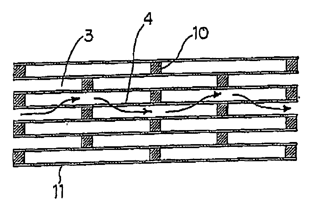
[0117]To 100 parts by mass of cordierite forming material prepared by combining a plurality of materials from tale, kaolin, fired kaolin, alumina, aluminum hydroxide and silica to mix the material at a predetermined ratio so that a chemical composition of the material contained 42 to 56 mass % of SiO2, 30 to 45 mass % of Al2O3 and 12 to 16 mass % of MgO, 12 to 25 parts by mass of graphite and 5 to 15 parts by mass of synthetic resin were added as pore formers. Furthermore, after appropriate amounts of methyl celluloses and surfactant were added, water was added, and the material was kneaded to thereby prepare a clay. After evacuating and deaerating the prepared clay, the clay was extruded to thereby obtain a formed honeycomb body. The resultant formed honeycomb body was dried and then fired in a maximum temperature range of 1400 to 1430° C. to thereby obtain a fired honeycomb body. Cells of the resultant fired honeycomb body were filled with a plugging material and fired again so as...

example 2

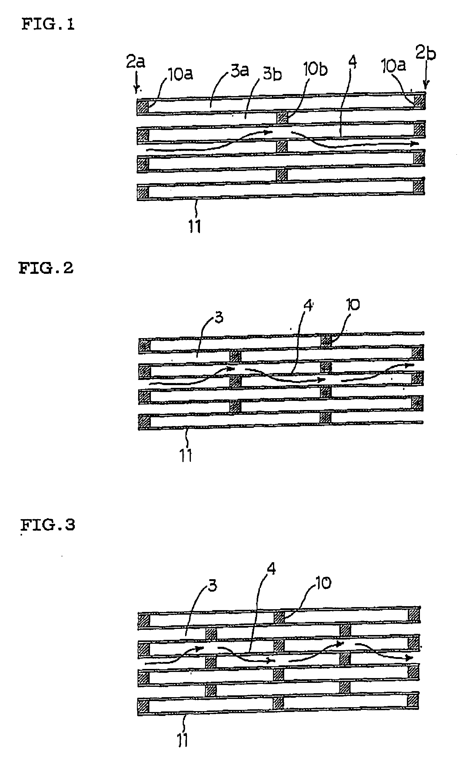
[0119]A honeycomb catalytic body was prepared in the same manner as in Example 1 except that a plugging agent was charged so as to obtain a plugged state as shown in FIG. 2.

example 3

[0120]A honeycomb catalytic body was prepared in the same manner as in Example 1 except that a plugging agent was charged so as to obtain a plugged state as shown in FIG. 3.


PUM

PropertyMeasurementUnit
maximum image distanceaaaaaaaaaa
image distanceaaaaaaaaaa
porosityaaaaaaaaaa

Abstract

There are disclosed a honeycomb catalytic body to which a wall flow structure is applied so that a fluid such as an exhaust gas passes through a partition wall twice or more, and a honeycomb structure for use as a catalyst carrier of the honeycomb catalytic body in which a pore characteristic and the like are appropriately adjusted as the catalytic body. In a honeycomb structure 11 including porous partition walls 4 arranged so as to form a plurality of cells 3 which communicate between two end surfaces of the honeycomb structure and having a large number of pores; and plugging portions 10 arranged so as to plug at least a part of the plurality of cells 3 at any position in a length direction of the cells, an average maximum image distance of the partition walls is larger than 40 μm, and the plugging portions 10 are arranged so that at least a part of a fluid which has entered the cells from one end surface passes through the partition wall 4 twice or more, and is then discharged from the other end portion.

Description

BACKGROUND OF THE INVENTION[0001]1. Field of the Invention[0002]The present invention relates to a honeycomb structure and a honeycomb catalytic body for preferable use in purification of unpurified components such as carbon monoxide (CO), hydrocarbon (HC), nitrogen oxide (NOx) and sulfur oxide (SOx) included in exhaust gases discharged from fixed engines, combustion devices and the like for cars, construction machines and industries.[0003]2. Description of the Related Art[0004]At present, a catalytic body of a honeycomb structure (a honeycomb catalytic body) has been used in purifying exhaust gases discharged from various engines and the like. As shown in FIG. 17, this honeycomb catalytic body has a structure in which a catalytic layer 15 is carried by the surface of a partition wall 4 constituting a cell (a channel) 3. As shown in FIGS. 15, 16, to purify the exhaust gas by use of a honeycomb catalytic body 60 (a honeycomb structure 11), the exhaust gas is passed through the cells ...

Claims


Application Information

Patent Timeline
Patent Type & Authority Applications(United States)
IPC IPC(8): B32B3/12
CPCB01D46/2425Y10T428/24149B01D46/2459B01D46/247B01D53/9454B01D2046/2433B01D2046/2437B01D2046/2496B01J23/42B01J23/464B01J23/63B01J35/04B01J37/0018B01J37/0215Y02T10/22Y10T428/24157B01D46/2429Y02T10/12B01D46/24492B01D46/24491B01D46/2498B01D46/2484B01D46/2482
Inventor MIYAIRI, YUKIONODA, NAOMIMAKINO, MIKIO
Owner NGK INSULATORS LTD
Why Eureka
Try Eureka