Microfluidic interface for highly parallel addressing of sensing arrays

Active Publication Date: 2007-10-04
UNIV OF UTAH RES FOUND
View PDF24 Cites 50 Cited by
  • Summary
  • Abstract
  • Description
  • Claims
  • Application Information

AI Technical Summary

Benefits of technology

[0013] The present invention includes a method and apparatus capable of patterning the surface of microarrays with a high-concentration of individually addressed spots. The present invention includes a method of manipulating the inventive apparatus b

Problems solved by technology

In the '432 patent, one end of the capillaries may be attached to a reservoir; however there is no return path for the substance that is spotted and therefore no way to flow a substance over a substrate to increase the spot deposition density.
While prior art systems are capable of producing multiple spots of a controlled size, if the desired molecule for deposition is present in very low concentration, the total number of desired molecules that can be deposited on the surface is severely limited for a single spot.
The Perkin-Elmer BIOCHIP ARRAYER® uses “ink jet printing” technology, but that method has the same concentration limitation as the “pens.”
For an example of such a system see, U.S. P

Method used


Image

  • Microfluidic interface for highly parallel addressing of sensing arrays
  • Microfluidic interface for highly parallel addressing of sensing arrays
  • Microfluidic interface for highly parallel addressing of sensing arrays

Examples


example 1

Single Orifice Spotter

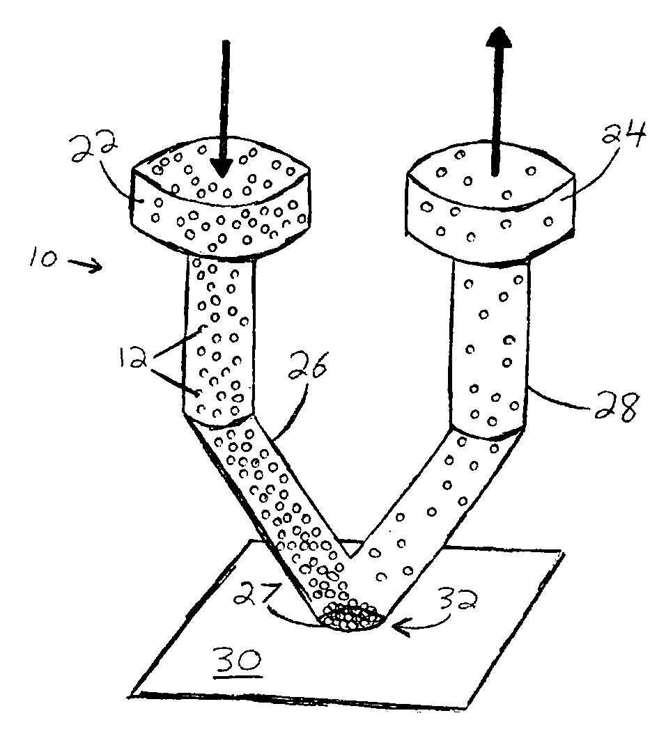
[0087] Deposition of Protein A was attempted with a single orifice spotter similar to that shown in FIG. 3, to validate the design concept displayed in FIG. 1. Protein A (ImmunoPure Protein A, cat #21181, Pierce Inc.) was biotinylated with Biotin (EZ-Link Sulfo-NHS-Biotin, cat #21217, Pierce Inc.) to provide specific adhesion to a surface plasmon resonance (SPR) streptavidin gold chip (8500 streptavidin affinity chip, part #4346388, AB). The protein solution was diluted to a concentration of 0.15 μg / mL in 0.1×PBS buffer (0.19 mM NaH2PO4, 0.81 mM Na2HPO4, pH 7.4 and 15 mM NaCl) and supplemented with 100 μg / mL BSA to prevent non-specific adhesion. To recirculate the solution over the chip surface, 200 μL of protein A solution was loaded into a Phynexus MicroExtractor 100 syringe pump and flowed continuously back and forth through the spotter at 75 μL / min for 1 hour. A wash step was then performed using 800 μL of 0.1×PBS with 100 μg / mL BSA. At the end, the sample...

example 2

Four Orifice Spotter

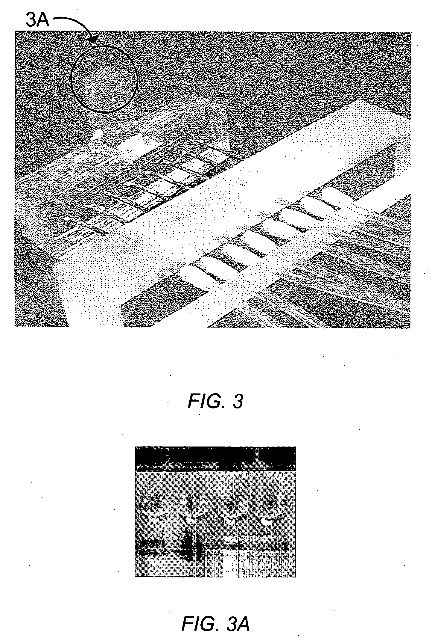
[0089] An embodiment of a four orifice spotter is shown in FIGS. 3 & 3A. ImmunoPure Protein A (Pierce, cat #21181) was prepared in PBS buffer (20 mM NaH2PO4 / Na2HPO4 pH 7.4, 150 mM NaCl) at a concentration of 5 mg / mL. The ports that address each spot were connected together using tubing so the same sample was flowed across the four spots. The spotter was mounted over a FLEXchip plain gold surface and the sample was flowed over all four spots manually using a syringe for approximately 1 hour. At the end, the spots were washed using PBS buffer and the chip was mounted according to the instructions of the manufacturer.

[0090] The protein A-adsorbed chip was inserted in the FLEXchip array instrument. The four areas where protein A was deposited were visible, so the spots could be assigned where the immobilized material is located. An example of the assigned spots is shown in FIG. 4A; the four spots labeled 1-4 correspond to immobilized protein A spots, while the rema...

example 3

Test Methods and Results

[0097] The same sample of protein A that was used in Example 2 was also used for this assay [ImmunoPure Protein A (Pierce, cat #21181) at 5 mg.mL in PBS buffer (20 mM NaH2PO4 / Na2HPO4 pH 7.4, 150 mM NaCl)]. The spotting was performed over a plain gold FLEXchip and the protein A was flowed over the chip for approximately 1 hour. At the end the spots were washed using PBS buffer and dried. The resulting spots are shown FIG. 8.

[0098] Seven of the eight protein A spots were visible after the chip was inserted into the FLEXchip array instrument. The spots were 200 microns square, roughly half the size of the spots deposited over with the four orifice spotter. A grid of 10×10 spots was assigned to enclose the eight protein A spots and the surrounding area (although the spotting pattern is a 10×10 grid, inclusion of the reference spots results in a grid of 21×11, as shown in the histogram). For reference, the protein A spots are located over the seventh column, spo...


PUM


Abstract

Disclosed is a spotter device and methods for the formation of microassays, biochips, biosensors, and cell cultures. The spotter may be used to deposit highly concentrated spots of protein or other materials on a microarray slide, wafer, or other surface. It may also be used to perform various chemistry steps on the same spots. The spotter increases the surface density of substances at each spot by directing a flow the desired substance (or a solution thereof) over the spot area until surface saturation is accomplished. The spotter may be loaded by well plate handling equipment. The spotter uses wells, microfluidic conduits, and orifices to deposit proteins, other biomolecules, or chemicals on a spot on a separate surface. Each orifice is connected to two wells via microconduits. When the spotter contacts a surface, a seal is formed between the orifices and the surface. The same or different substances may be flowed across each orifice. Any number of orifices may be incorporated into a spotter. The spotter is particularly useful for depositing proteins in high concentrations on a surface, since the spotter may be placed on a surface for an extended period of time.

Description

STATEMENT REGARDING FEDERALLY SPONSORED RESEARCH OR DEVELOPMENT [0001] Work described herein was supported National Science Foundation Grant #DGE 9987616. The United States Government may have certain rights in the inventionTECHNICAL FIELD [0002] The present invention relates generally to biotechnology, more specifically to building microassays, biochips, and biosensors. In particular, the present invention encompasses a device with microfluidic channels for the deposition of a substance on a substrate. BACKGROUND [0003] In recent years, a large number of biological / chemical analysis techniques have been demonstrated using micro-scale systems and have been implemented using micromachining technology. The rationale for using microscale technologies in analytical instrumentation includes reduction in instrument size and cost, reduction in sample and reagent volume, reduction in analysis time, increase in analysis throughput, and the possibility of integration of sample preparation and...

Claims


Application Information

Patent Timeline
IPC IPC(8): C12M3/00G01D15/02
CPCB01J19/0046G01N33/553B01L3/5025B01L3/502715B01L3/50273B01L2200/021B01L2300/0636B01L2300/0819B01L2300/0822B01L2300/0877B01L2400/0487G01N35/1074G01N2035/00158G01N2035/1039C12N15/1093B01L3/0293Y10T436/2575
Inventor CHANG-YEN, DAVID A.NATARAJAN, SRIRAMECKMAN, JOSHGALE, BRUCE K.MYSZKA, DAVID
Owner UNIV OF UTAH RES FOUND
Why Eureka
Try Eureka