Method and system for providing multimedia information on demand over wide area networks

a multimedia video and audio data and wide area network technology, applied in data switching networks, selective content distribution, instruments, etc., can solve the problems of increasing the cost of the system, unable to process the large number of streams that are required, and floating point support adds to the system cost, so as to increase the overall throughput, reduce the time required, and increase the latency of copying from cache into the server

Inactive Publication Date: 2007-10-04
EMC IP HLDG CO LLC
View PDF56 Cites 13 Cited by
  • Summary
  • Abstract
  • Description
  • Claims
  • Application Information

AI Technical Summary

Benefits of technology

[0038] The above provides advantages to most any storage control logic that involves multiple servers or disk connections. Moving the individual functional components of the controller device onto the switching fabric has some specific benefits, including:
[0039] Moving the cache management logic onto the controller device means the synchronization communication between individual controller devices would enjoy reduced latency;
[0040] Moving the cache onto the controller device improves the efficiency of cache pooling—the concept of getting data from remote controller devices without the requirement of going to disk because of reduced latency and, potentially, increased bandwidth. In applications such as video streaming, there is the opportunity for an improved Quality of Service (Q of S);
[0041] Moving the RAID engine onto the controller device increases the overall throughput by allowing the additional RAID I / O streams (e.g. two streams involved with mirroring across redundancy groups) to be sent in parallel with other communications. In an HBA implementation, all streams must share a single channel on the external network (e.g. Fibrechannel). There is a balance here. Placing the cache on the blades (within the switching fabric) may increase the latency of copying from cache into the server. However, as the block speed of the physical network increases, this generally becomes less of an issue; and
[0042] Moving the administrative functionality onto the controller device generally reduces the time required for administrative functions such as replication and backups.

Problems solved by technology

While the end-user (client) system and the front-end network system infrastructure is evolving rapidly to meet the requirement of interactive multimedia services, current server systems continue to be expensive and impractical for delivering these services because of the limited capacity of the server system.
Current server systems are unable to process the large number of streams that are required by streaming multimedia and video services.
The floating-point support adds to the cost of the system without providing any benefit to the delivery of multimedia video and audio data.
However, the above mentioned improvements may typically only improve the overall performance of current video server systems by a factor of two or four times, whereas the current need in the Industry requires improvements in the range of 100 to 1000 times current technology to make the interactive streaming video services economically feasible.
Failure to maintain Quality of Service may typically result in an image that is jerky or distorted.
Traditional server system architectures have not been equipped with the functionality necessary for the implementation of providing Quality of Service on a large scale (more than one dedicated server for each client on the network).
However, the IBM system described above provides for the storage of data onto switches, it does not allow the individual switches to cooperate together as a distributed architecture in order to pool bandwidth together to supply the backbone network.
Also, in the '085 patent, the individual switches are not able to work together to distribute a delivery request over multiple switches for load balancing and streaming of the requested data.

Method used


Image

  • Method and system for providing multimedia information on demand over wide area networks
  • Method and system for providing multimedia information on demand over wide area networks
  • Method and system for providing multimedia information on demand over wide area networks

Examples


Embodiment Construction

[0072] In the following description, although the use of a packet-switched network which transports only fixed size cells is described, the following can easily be adapted for use in networks which transport variable size packets or in circuit switched network.

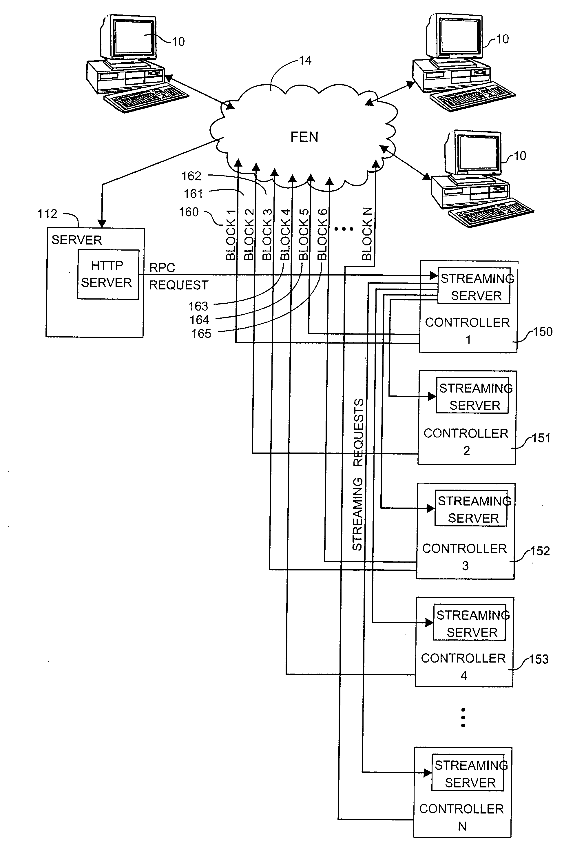
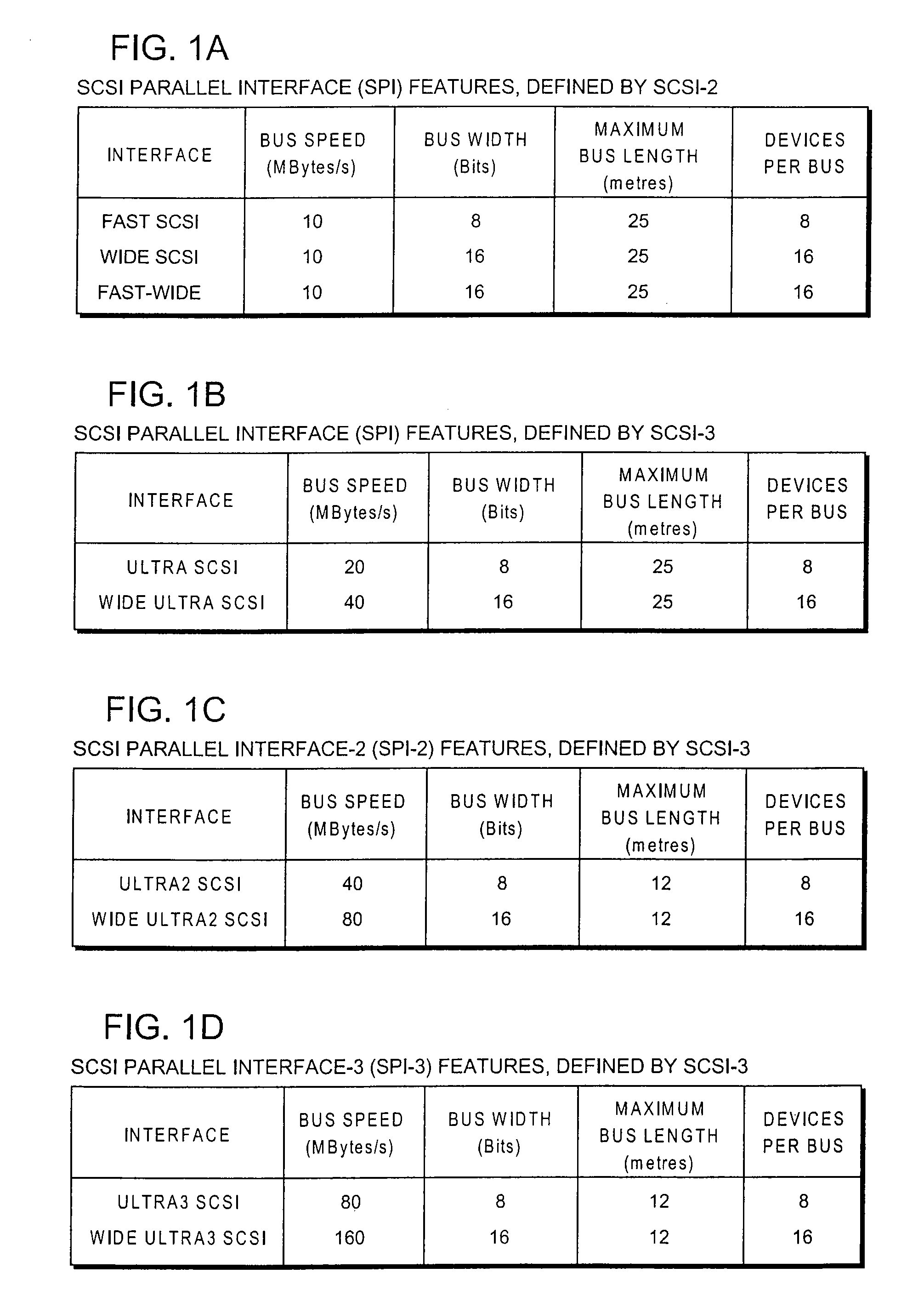
[0073] The present invention includes two components. the first component includes the messaging scheme (hereinafter, “Messaging Protocols”) for communicating the video data or other data content from the controller card to the client with the intermittent interaction software protocols: In order to accommodate all of these features and maintain backward compatibility, SCSI-3 expanded to become a “family” of standards, categorized as either a logical or a physical interface.

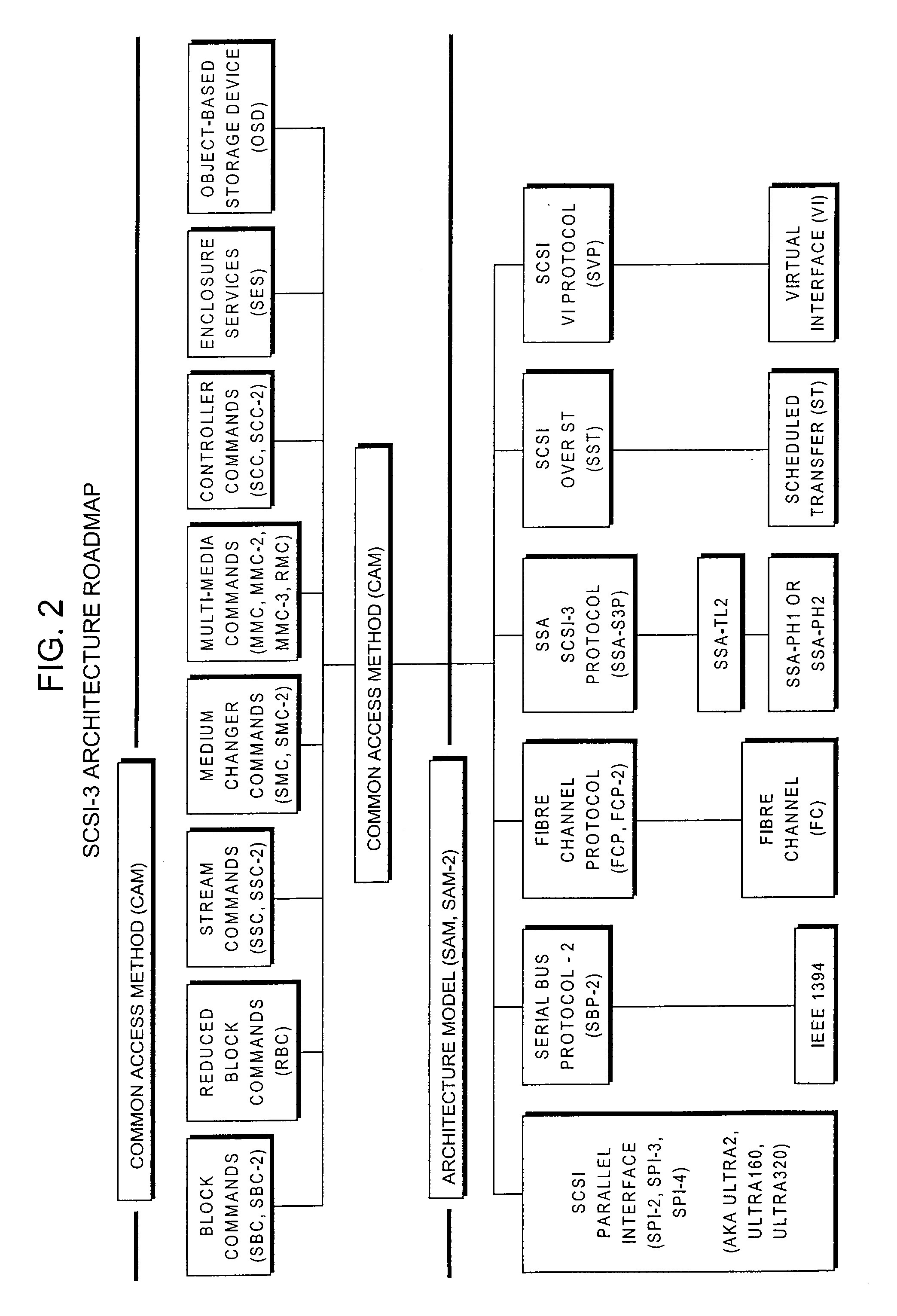
[0074] Referring to FIG. 2, the scope of the SCSI-3 architecture is illustrated. As shown in FIG. 2, three physical interfaces are defined by the SCSI Architecture Model (SAM) of SCSI-3 that enable serialized transport of SCSI channel protocol traffic: 13...


PUM


Abstract

Systems and methods for delivering streaming data content to a client device over a data communication network in response to a request for the data content from the client device. The client request is received by a server or a controller device that is typically located on a network switch device. If received by a server, the server sends a request to the controller device to control the transfer of the requested data to the client. The controller device includes the processing capability required for retrieving the streaming data and delivering the streaming data directly to the client device without involving the server system. In some cases, the controller device mirrors the data request to another controller device to handle the data processing and delivery functions. In other cases, the controller device coordinates the delivery of the requested data using one or more other similar controller devices in a pipelined fashion.

Description

CROSS-REFERENCES TO RELATED APPLICATIONS [0001] This application is related to, and claims priority from, U.S. Provisional Patent Application Ser. No. 60 / 191,237, filed Mar. 22, 2000, entitled “STORAGE ROUTING AND EXTENDABLE SCREENING SERVER SYSTEMS AND METHODS FOR IMPLEMENTING THE SAME,” the disclosure of which is hereby incorporated by reference in its entirety.BACKGROUND OF THE INVENTION [0002] The present invention relates to Storage Area Networks (SANs). In particular, the present invention relates to methods and systems for providing multimedia data, such as video data, to a client making a request to a data delivery system over a communication network such as a Wide Area Network (WAN). [0003] The Communication Network used to deliver multimedia and video to an end-user (client) typically includes the following three main components: a back-end network comprised of a server system, an end-user system, and a front-end network for connecting a plurality of end-users (clients) to...

Claims


Application Information

Patent Timeline
Patent Type & Authority Applications(United States)
IPC IPC(8): G06F15/16H04L12/56H04L29/06H04L29/08H04N21/226H04N21/232H04N21/472
CPCH04L12/5601H04L29/06027H04L47/10H04L47/36H04L63/0428H04N21/226H04L69/329H04N21/472H04L65/4084H04L67/1095H04L67/42H04L67/1097H04N21/232H04L65/612H04L47/43H04L65/1101H04L67/01
Inventor KARPOFF, WAYNE T.
Owner EMC IP HLDG CO LLC
Why Eureka
Try Eureka