Threaded joint for steel pipes

a technology for connecting steel pipes and threaded joints, which is applied in the direction of hose connections, screw threaded joints, mechanical equipment, etc., can solve the problems of weak contact at the thread root, plastic deformation, and insufficient tightening, so as to improve the compression resistance of a rugged thread, the effect of ensuring the resistance to external pressure and torque variation

Active Publication Date: 2007-10-11
NIPPON STEEL CORP +1
View PDF9 Cites 17 Cited by
  • Summary
  • Abstract
  • Description
  • Claims
  • Application Information

AI Technical Summary

Benefits of technology

[0093] According to the present invention, the excellent compression resistance of a rugged thread can be maintained while torque variation, which is a problem of rugged threads, can be restrained to a low level capable of being manufactured with present-day tolerance control techniques, resistance to external pressure can be guaranteed, and operability in the field and particularly make-up speed can be increased.

Problems solved by technology

In the case of the above-described buttress thread, there is strong contact at the thread root due to the interference of the thread portions.
If the torque shoulder portions do not abut, a make-up force in the axial direction is not generated, and the amount of tightening becomes inadequate, whereas if the torque shoulder portions abut each other too strongly, the torque shoulder portions end up undergoing plastic deformation, and the sealing properties of the adjoining metal seal portions end up decreasing.
In addition, in recent years, due to the deepening of oil wells or excavation and production in locations having poor soil properties, there are cases in which oil well pipes undergo large external pressures due to the load from fluids other than products (crude oil and natural gas) outside the well bore or contraction and collapse of the well.
If make-up of a joint requires one minute extra, for example, overall installation ends up requiring an extra 6 to 12 hours.
This results in additional labor costs for field operations and costs for equipment rental, leading to an increase in costs.
However, with a rugged thread, the variation in torque due to thread tolerances is extremely large, so it is difficult to set a suitable make-up torque.
However, in extreme cases, the torque at the start of shoulder contact (referred to as the shouldering torque) of a product within tolerances exceeds the torque at which the shoulders undergo plastic deformation (referred to below as overtorque) for another product which is within tolerances, and a suitable torque no longer exists.
The above-described situation (generally referred to as the high shouldering problem) is unavoidable with present-day manufacturing control techniques (allowable manufacturing tolerances) particularly with respect to small-diameter rugged threads having an outer diameter of 5 inches or less.
None of the above-described prior art documents has any description with respect to this high shouldering problem, so they do not disclose a method for solving it.
However, in Patent Document 3, it is necessary to perform swaging over a considerable length of the pipe end (probably around 100-200 mm), so a horizontal rolling mill of extremely large power is required, and the swaging die rapidly deteriorates, so there is concern of manufacturing costs becoming quite high.
In addition, the inner diameter of a joint is reduced by considerable ratio, so turbulence when internal fluids pass through the joint portion becomes severe and there is a concern of its causing erosion.
In addition, in the case of an oil well pipe, the size of pipe which can be inserted into its interior decreases, so the string design ends up being having extremely poor efficiency.
However, the above-described prior art only improves the ease of make-up, and it cannot be said to improve resistance to compression.

Method used


Image

  • Threaded joint for steel pipes
  • Threaded joint for steel pipes
  • Threaded joint for steel pipes

Examples


example

Example 1

[0159] In order to demonstrate the effects of the present invention more concretely, the following numerical simulation analysis by the elasto-plastic finite element method and thread cutting test were carried out.

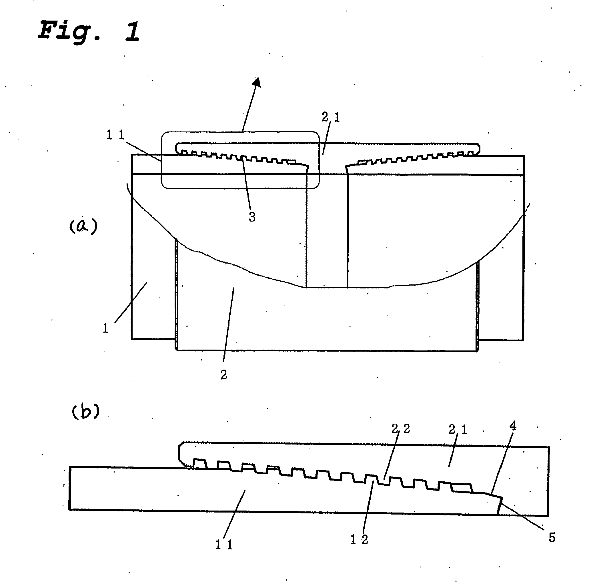
[0160] The subject of evaluation was the coupling-type threaded joint for oil well pipes shown in FIG. 1. It was a joint for a 5-½ inch #20 pipes (outer diameter of 139.7 mm, wall thickness of 9.17 mm) joint.

[0161] The material was that having the API specification P110. In finite element analysis, it was treated as an elasto-plastic body with an isotropic hardness, and it was numerically modeled as having a coefficient of elasticity of 210000 MPa and having a 0.2% strength equal to the nominal yield strength of 110 ksi (758 MPa).

[0162] Table 1 shows the joints on which evaluation was carried out. The shapes of the metal seal portions and the torque shoulder portions being analyzed were slightly different from each other, but the minimum values and the maximum...

example 2

[0171] In this example, Example 1 was repeated, and numerical simulation analysis by the elasto-plastic finite element method was carried out.

[0172] Table 3 shows the joints on which evaluation was carried out. Sample 6 which was a joint according to the present invention had a rugged thread as a first thread portion of a two-level thread and a buttress thread as a second thread portion. A metal seal was disposed only in portion B, and a torque shoulder was disposed only in portion C.

[0173] The joints of Samples 7-8 were one-level threads like that shown in FIG. 1. They had a structure in which a metal seal and a torque shoulder were provided at the end portion of a pin.

[0174] The seal shape and the torque shoulder shape of the joints of Samples 6-8 were each slightly different from those described above, but the minimum value and maximum value of the interference imparted to the metal seal portion were all made the same.

[0175] Of the thread shapes, Samples 6-8 each had a thread...

example 3

[0181] In this example, Example 1 was repeated, and numerical simulation analysis by the elasto-plastic finite element method and estimation of the time for thread make-up were carried out.

[0182] Table 5 shows the joint on which evaluation was carried out. Ones shown in FIG. 12 were used as representative examples of the present invention. The shapes of the metal seal portion and the torque shoulder portion being analyzed had slight differences, but the minimum and the maximum values of the seal interference were the same for each.

[0183] Of the thread shapes which were analyzed, the thread pitch was 5.08 mm and the thread taper was 1 / 18 for each one.

TABLE 5Manufacturingtoleranceof threadinterferenceLoadStabbingSample(overflankflankThreadNo.diameter)angleangleheightComments90.2mm+3°35°1.6mmThread mode ofFIG. 12(a)100.2mm+3°35°1.6mmThread mode ofFIG. 12(e)110.2mm+3°35°1.6mmThread mode ofFIG. 12(i)120.2mm+3°35°1.6mmAll single-startrugged threads130.19mm−3°10°1.58mmAll single-startb...


PUM


Abstract

In a threaded joint for steel pipes which are connected by threaded engagement of a pin member having a tapered male thread, a metal seal-forming portion, and a torque shoulder-forming portion on the end of a pipe, and a box member having a tapered female thread, a metal seal-forming portion, and a torque shoulder forming-portion corresponding to these on the end of a pipe, a buttress thread having contact at the load flanks and the thread root surface and gaps at the thread crest surface and the stabbing flanks is mixed in a single joint with a rugged thread having contact at the load flanks and stabbing flanks and having gaps at the thread root surface and thread crest surface.

Description

TECHNICAL FIELD [0001] This invention relates to a threaded joint for connecting steel pipes such as oil well pipes, riser pipes, and line pipes used in the exploration and production of oil wells and gas wells, and in particular it relates to a threaded joint for steel pipes having excellent resistance to compression and resistance to external pressure, ability to seal against internal pressure and external pressure under a compressive load, and preferably also excellent operability during installation in the field. BACKGROUND OF THE INVENTION [0002] Threaded joints are typically used as a means for connecting oil well pipes. In recent years, there has been increasing application of threaded joints to steel pipes which have conventionally been connected by welding, such as riser pipes and line pipes. [0003] Up to now, a standard threaded joint was one meeting API (American Petroleum Institute) standards, but in recent years, the environments of excavation and production of crude oi...

Claims


Application Information

Patent Timeline
Patent Type & Authority Applications(United States)
IPC IPC(8): F16L15/06
CPCE21B17/042F16L15/06F16L15/004
Inventor SUGINO, MASAAKIYAMAMOTO, MIYUKIIWAMOTO, MICHIHIKONAGASAKU, SHIGEO
Owner NIPPON STEEL CORP
Why Eureka
Try Eureka