Microfluidic pumps and mixers driven by induced-charge electro-osmosis

a microfluidic pump and electro-osmosis technology, applied in the field of microfluidics, micrototalanalysis systems (tas), microelectromechanical systems, can solve the problems of irreversible failure, microfluidic devices employing dc electric fields, and typically have short lifetimes

Inactive Publication Date: 2007-10-18
MASSACHUSETTS INST OF TECH
View PDF31 Cites 39 Cited by
  • Summary
  • Abstract
  • Description
  • Claims
  • Application Information

AI Technical Summary

Problems solved by technology

This typically takes from seconds to minutes—far too slow for envisioned applications.
In spite of its appealing simplicity, however, there are several drawbacks to the use of DC electric fields, related to the fact that a steady current (J=σE) must exit in order to maintain a steady field because every electrolyte has a non-negligible bulk conductivity.
This can cause a variety of problems.
For example, the dissolution of the anode eventually destroys the electric circuit, causing irreversible failure.
Microfluidic devices employing DC electric fields thus typically have short lifetimes, which can be acceptable in some applications, such as one-time drug delivery, but not in others, such as μTAS.
A shorter lifetime also translates into a higher cost per unit of time of operation.
The dissolution of the anode also injects metallic ions into the fluid, which can present safety hazards in biomedical applications or can interfere with chemical reactions in μTAS.
Also, the depositions of ions at the cathode can lead to unstable deposits, which can break off or otherwise interfere with the bulk fluid.
Furthermore, electrochemical reactions at electrodes inevitably cause electrolyte concentration gradients, which create complicated and potentially unwanted secondary bulk electric fields, as well as secondary electrokinetic phenomena at surfaces.
Furthermore, the change in electrode polarity frustrates electrochemical reactions, helping avoid unwanted electrolysis reactions at the electrodes.
Although the available pumping techniques based on AC electric fields offer various advantages over DC methods, there are still serious drawbacks.
Foremost among these is the need to microfabricate complex patterned-surface electrodes with elaborate micro-circuitry, which can be more costly, difficult, and prone to failure than their very simple DC counterparts.
Another potential drawback is that patterned-surface devices are “hard-wired” into the electrical circuitry and the physical structure of the surface itself, rendering them less versatile.

Method used


Image

  • Microfluidic pumps and mixers driven by induced-charge electro-osmosis
  • Microfluidic pumps and mixers driven by induced-charge electro-osmosis
  • Microfluidic pumps and mixers driven by induced-charge electro-osmosis

Examples


example 1

Device Comprising Multiple Induced-Charge Electro-Osmotically driven Microfluidic Mixers

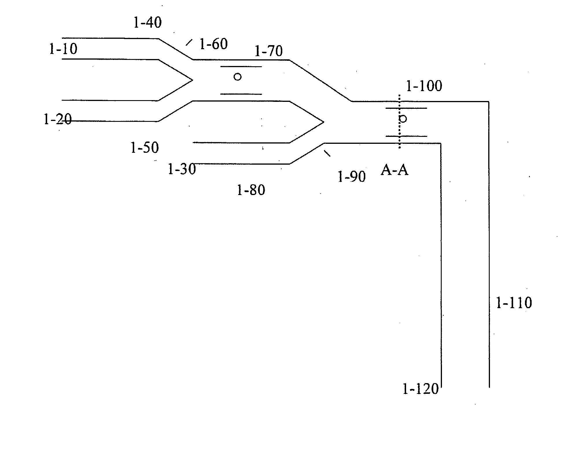
[0214] It is possible to create many permutations of a device comprising multiple induced-charge electro-osmotically driven microfluidic mixers or pumps, or a combination thereof, as will be appreciated by one skilled in the art, and as described hereinabove. One embodiment of such a device is a microfluidic two-stage mixer, as depicted in FIG. 1. The device will comprise inlet ports for the introduction of a sample, a reagent, a detecting moiety, a catalyst, or a combination thereof, or any agent whose introduction is desired. Such inlet ports may be constructed as depicted in the figure (1-10, 1-20, and 1-30). The inlet ports, in turn, may lead to channels (depicted at 1-40, 1-50, and 1-80 respectively, in the figure), which in this example serve to convey the introduced matter into another region of the device. Channels 1-40 and 1-50 may merge, for example as a Y-junction (1-60) and lead to a...

example 2

Analysis of Cellular Components

[0215] It will be appreciated by one skilled in the art that the device described in Example 1 may be useful in a wide array of applications. In one application, for example analysis of expressed proteins or nucleic acids in a single cell, inlet 1-10 is used to introduce a single cell in a buffer solution into the device. It will be appreciated by one skilled in the art that the inlet will be so constructed as to facilitate entry of singular cells, which are then conveyed to channel 1-40. Inlet 1-20 conveys a lysing agent. The lysing agent mixes with the cell and buffer solution in 1-70, causing cell lysis, and release of cellular contents. Inlet 1-80 conveys a fluorescent-tagged probe or antibody which mixes with the cellular contents in 1-100, resulting in specific labeling of cellular components. It is also envisioned that wash solutions are introduced in the inlet following a period of time of exposure to the labeled agent, or, another inlet which...

example 3

Construction of a Device Comprising Induced-Charge Electro-Osmotically Driven Microfluidic Mixers

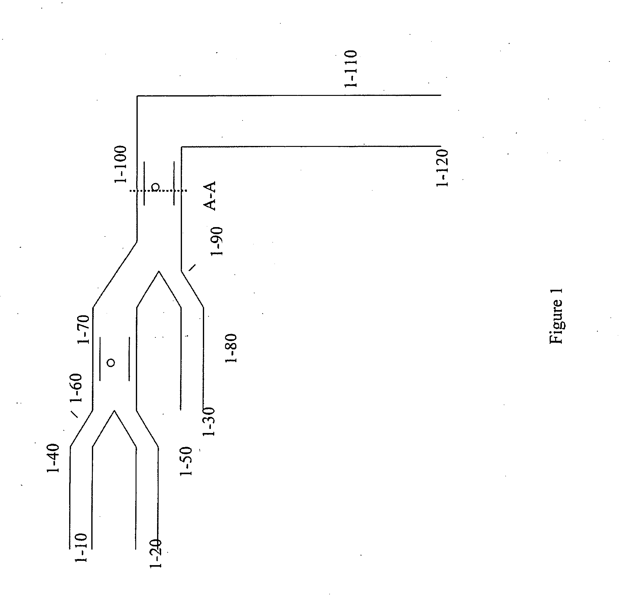
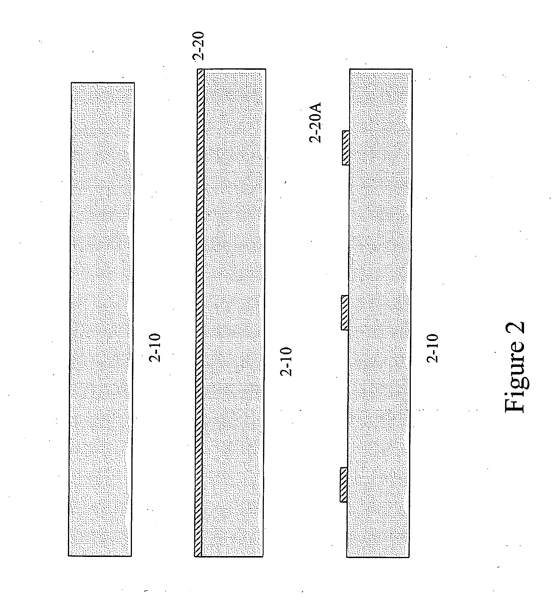
[0216] Many methods for fabricating devices as described herein will be apparent to one skilled in the art. One embodiment for such a means of construction is depicted in FIG. 2. The figure specifically describes fabrication of the device outlined in Example 1, FIG. 1, at the region of the device labeled as section A-A.

[0217] The starting substrate 2-10 is a 0.5 μm thick four-inch diameter double-side polished borofloat glass wafer. Substrate 2-10 is cleaned in 3:1 sulfuric acid:hydrogen peroxide to remove any organic material from the surface. The substrate 2-10 is then oxygen plasma ashed for 5 minutes to roughen the surface.

[0218] Following preparation of the substrate, a gold layer 2-20 is e-beam evaporated onto the substrate. Polymer photoresist is deposited onto the gold layer 2-20 and patterned using a chromium photomask. The patterned photoresist is then used as a masking mate...


PUM

PropertyMeasurementUnit
radiusaaaaaaaaaa
velocitiesaaaaaaaaaa
90° angleaaaaaaaaaa

Abstract

This invention provides devices and apparatuses comprising the same, for the mixing and pumping of relatively small volumes of fluid. Such devices utilize nonlinear electrokinetics as a primary mechanism for driving fluid flow. Methods of cellular analysis and high-throughput, multi-step product formation using, devices of this invention are described.

Description

CROSS REFERENCE TO RELATED APPLICATIONS [0001] This application is a Continuation-In-Part of U.S. application Ser. No. 10 / 319,949, filed on Dec. 16, 2002, which claims priority from U.S. Provisional Application Ser. No. 60 / 341,777 filed on Dec. 18, 2001; and claims the benefit of U.S. Provisional Application Ser. No. 60 / 620,000, filed Oct. 19, 2004 which are incorporated in their entirety herein by reference.GOVERNMENT SUPPORT [0002] This invention was made with U.S. Government support under Grant Number DAAD-19-02-002, awarded by US Army Research Office. The government has certain rights in the invention.BACKGROUND OF THE INVENTION [0003] The invention relates to the fields of microfluidics, micro-total-analysis systems (μTAS) and micro-electro-mechanical systems (MEMS), in particular microfluidic pumps and mixers driven by induced-charge electro-osmosis. [0004] The ability to transport fluids in micron-sized channels is essential for many emerging technologies, such as in vivo dru...

Claims


Application Information

Patent Timeline
Patent Type & Authority Applications(United States)
IPC IPC(8): C07K1/26B01D59/42G01N27/00
CPCB01F13/0076B01L3/50273B01L3/502746F04B19/006B01L2400/0418B01L2400/086B01L2300/0867B01F33/3031
Inventor LEVITAN, JEREMYBAZANT, MARTIN Z.SCHMIDT, MARTINTHORSEN, TODD
Owner MASSACHUSETTS INST OF TECH
Why Eureka
Try Eureka