Pipe pig formed of frozen product

a technology of pipe pigs and products, which is applied in the direction of cleaning processes and equipment, lighting and heating equipment, cleaning heat-transfer devices, etc., can solve the problems of significant quantity of product in the piping system becoming waste, unable to economically recover for later use, and loss of product, etc., to achieve the effect of minimizing product losses

Inactive Publication Date: 2002-11-26
KIHOLM ROBERT
View PDF27 Cites 25 Cited by
  • Summary
  • Abstract
  • Description
  • Claims
  • Application Information

AI Technical Summary

Benefits of technology

An object of the invention is that the pipe pig is employed as an instrument for product recovery in a piping system. The use of the pipe pig in this way has the advantage of minimizing product losses during product change-out or interruption that would conventionally result in the loss of a significant quantity of product that must be used to flush the pipe line. With product recovery using the pipe pig method of the present invention, the amount of waste product that must be discarded from a piping system when the system is shut down, or a change is made from one product to another, is minimized.
An additional advantage of the invention is that the pipe-pig is formed from at least a component of the process stream flowing within the pipe. This eliminates the need to retrieve the pig from the system. The frozen pipe pig simply melts when it reaches its destination or if it becomes inadvertently lodged within the pipe.

Problems solved by technology

The purging of a piping systems results in lost product unless a system of "product recovery" is employed.
Current product recovery systems are burdened with serious problems.
For piping systems, the "product recovery problem" usually means that periodically, a significant quantity of product in the piping system becomes waste that cannot be economically recovered for later use.
The product recovery problem typically arises in several situations with piping system designs.
For example, if a piping system is used to fill tanks or containers with a variety of different products over the course of a day or a week, then each time a run for one product ends and a run for a different product begins, a considerable amount of both products becomes unrecoverable waste.
Any compromise in this purity or control translates to unrecoverable waste at, the end of each work day, or product change or alteration.
In the case of food and beverage products, this unrecoverable waste is most often dumped down the drain.
The "drain dumping" disposal method costs the processor more than just the value of the wasted product, because this wasted product must be treated before it is reintroduced back into the environment.
The high sugar or carbohydrate content of most wasted food products then causes a population explosion in the bacteria at the sewage treatment facility.
Anaerobic bacteria create offensive odors, and are less efficient than aerobic bacteria at disposing of sewage waste.
Sewage treatment plants track precisely how much high sugar content industrial waste is dumped into their system, and they charge each company dumping this waste a considerable "biological oxygen demand" (BOD) assessment, which can significantly impact profit.
Sewage treatment plants also track precisely the quantity of suspended solids contained in the waste stream they receive from industrial sources, because the required treatment of these suspended solids is expensive.
For those processing companies that elect to build their own waste water treatment facility, they must incur the expense of building, maintaining, and operating their own facility.
This cost, which can be considerable, is often incurred primarily because of their decision to dump wasted product down the drain.

Method used


Image

  • Pipe pig formed of frozen product
  • Pipe pig formed of frozen product
  • Pipe pig formed of frozen product

Examples


Embodiment Construction

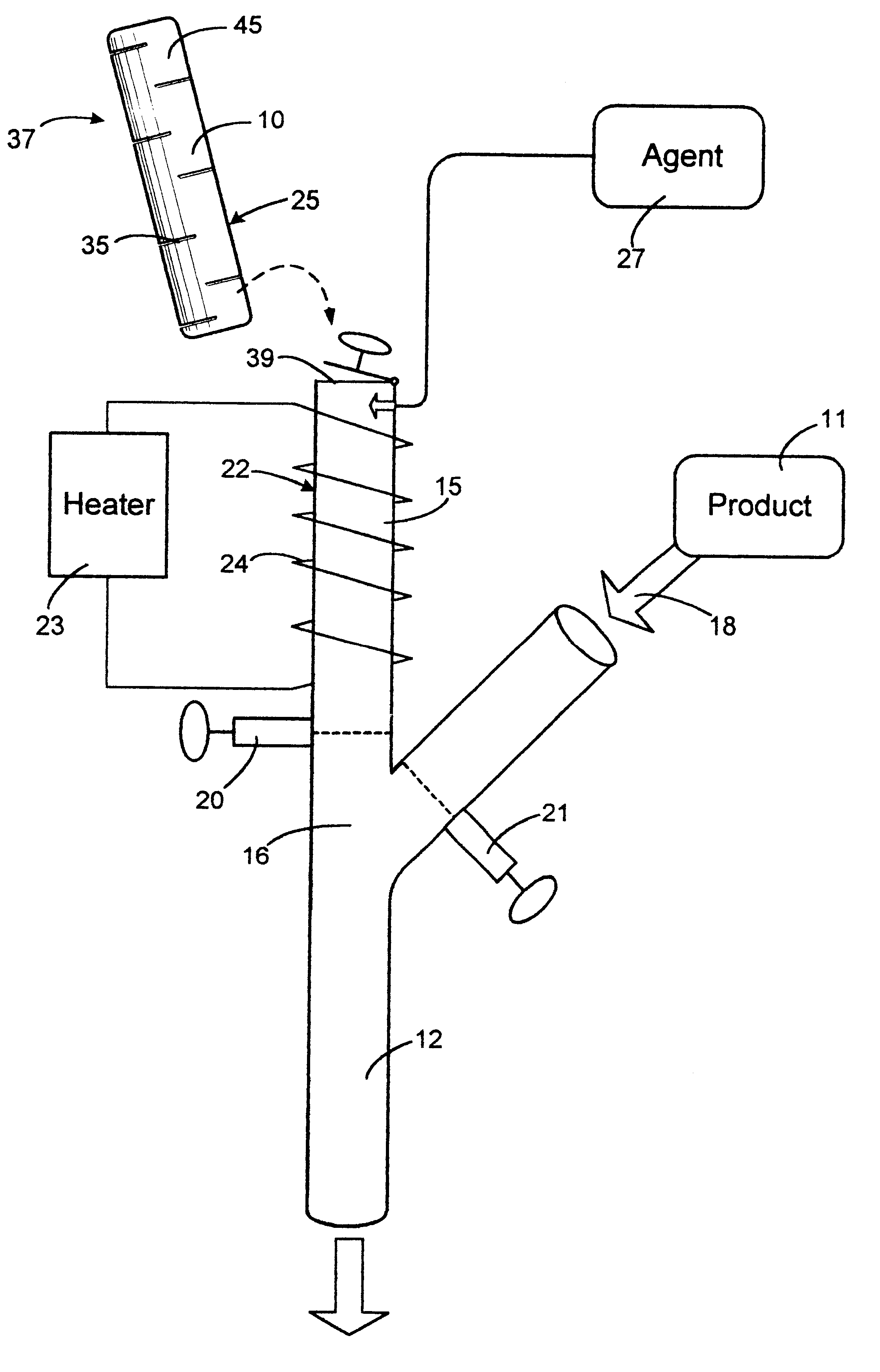
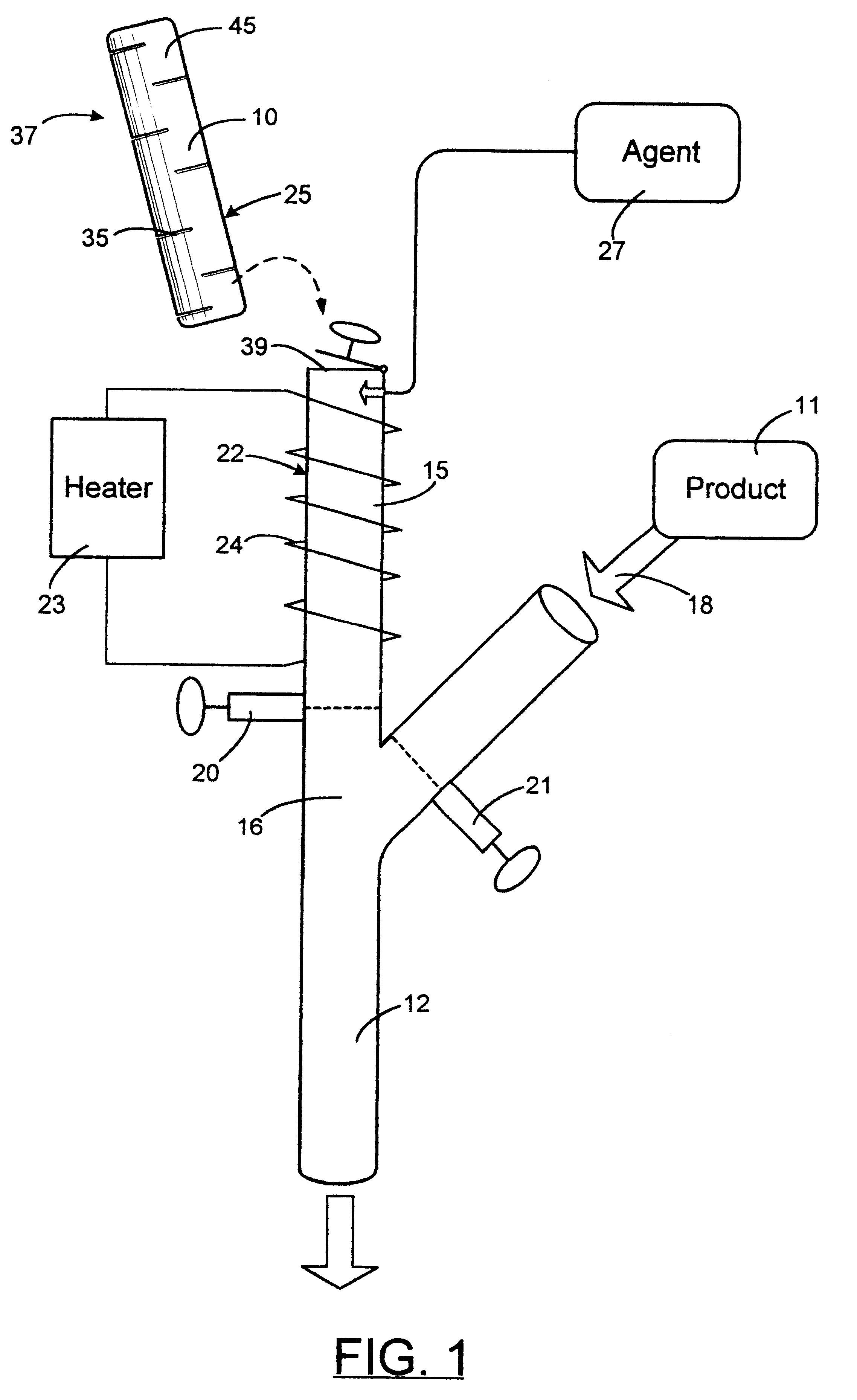
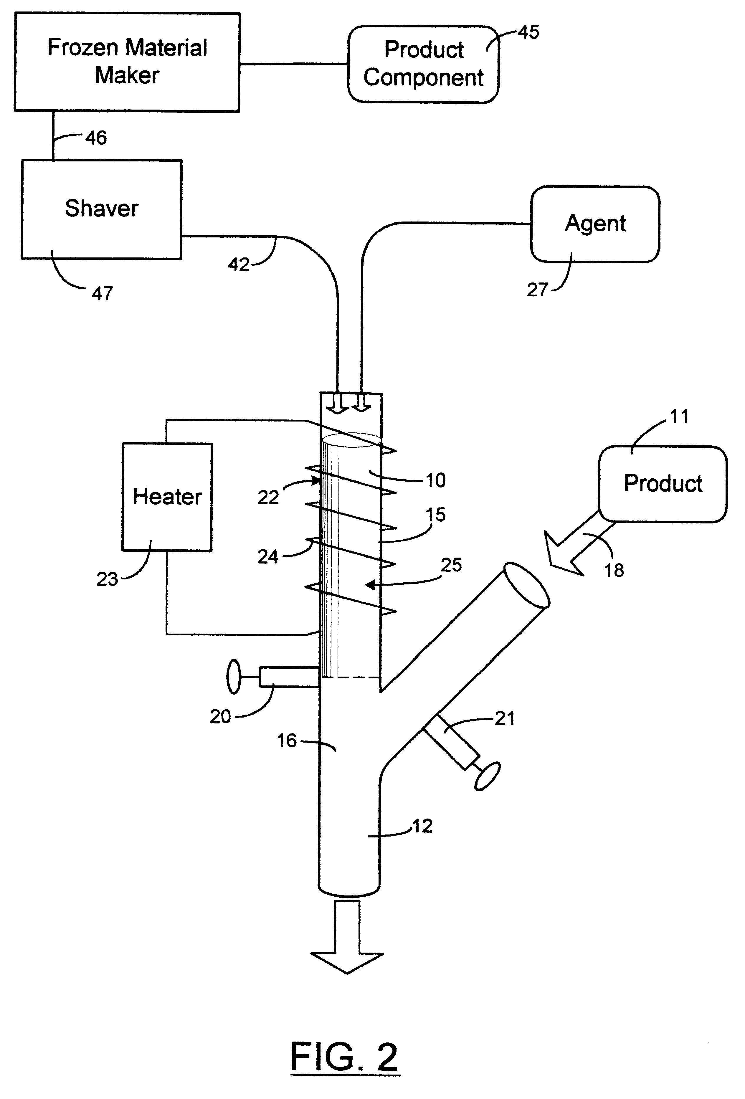
Industrial piping systems handle a wide variety of products, such as juice, juice concentrates, carbonated beverages, wine, beer, liquid medicines, and petroleum products--to name a few. The present invention, as shown in FIGS. 1 through 4, provides a method and apparatus for purging or flushing a product from a piping system by employing a pipe pig 10. The present invention allows for the product to be recovered without dilution, mixing or contamination with another liquid material. The pipe pig can be simply referred to as a "pig." The pig of the present invention is essentially a specialized slug of material that includes at least a single component of the product stream. The pig is frozen to a substantially solid form and so can be employed to push a product 11 within a pipe 12, ahead of the pig. The pipe, as shown in FIGS. 1 through 4, is a representation of a segment of the pipe, as would be found in a piping system employing the present invention. The individual and unique di...


PUM


Abstract

A method and apparatus for pipe pig that is employed in a piping system for the purpose of recovering product. The pipe pig, or simply "pig," is utilized to flush or purge a piping system, which includes a pipe that is normally filled with a product stream. The pig is a substantially solid slug that is introduced into the flow within the pipe. The pipe pig includes at least a component of a product stream and the pig is at least partially frozen to achieve its substantially solid form. The pipe pig is inserted or alternatively formed within a launch chamber that junctions with a pipe. A release valve is opened to allow the pig to enter the pipe. An exterior surface of the launch chamber can be heated to prevent the pig from sticking within the launch chamber or refrigerated to form the pig. The pipe pig can be propelled into the product stream or allowed to fall by gravity or suction alone. Articulations can also be formed into the pipe pig to allow the pig to bend along its length and so allow the pig to travel around elbows and bends in the pipe. Alternatively, a freezing agent can be injected into the pipe that contains the product stream to form the pig. With product recovery using the pig, piping system waste products are minimized.

Description

The invention relates field of product recovery and the flushing of pipelines used in any fluid transfer operation and especially in piping systems utilized in the filling of containers, including bottling lines, can lines and tank filling operations. More specifically, the present invention provides a method and apparatus for a pipe pig that is formed from a substantially frozen product or a component of the product.Typically, the transfer of liquid materials or products demands a periodic purging or flushing of the pipe carrying the materials. This pipe may be above or below ground, or in a plant setting. Often, a particular piping system must have the ability to handle a wide variety of products or at least periodic changes in product composition. These various products may differ in terms of their viscosity, ranging from high viscosity products such as peanut butter, salad dressings, and frozen concentrated juices; medium viscosity products, such as pharmaceutical products, petr...

Claims


Application Information

Patent Timeline
Patent Type & Authority Patents(United States)
IPC IPC(8): B08B9/02B08B9/04F16L55/40F16L55/26F16L55/46F28G1/12F28G1/00B08B9/055
CPCB08B9/0556F16L55/40F16L55/46F28G1/12
Inventor KIHOLM, ROBERT
Owner KIHOLM ROBERT
Why Eureka
Try Eureka