Methods for manufacturing electrochemical cell parts comprising material deposition processes

a technology of electrochemical cell parts and deposition processes, which is applied in the direction of cell components, sustainable manufacturing/processing, physical/chemical process catalysts, etc., can solve the problems of high density, high cost, and difficulty in manufacturing cell parts

Inactive Publication Date: 2007-10-18
AMERICAN GFM
View PDF1 Cites 11 Cited by
  • Summary
  • Abstract
  • Description
  • Claims
  • Application Information

AI Technical Summary

Benefits of technology

[0004] In a first set of representative embodiments, the present invention teaches a method for producing electrochemical cell parts, comprising the steps of: (a) applying one or more layers of a material on a substrate or a carrier surface; and (b) optionally removing the carrier surface; wherein the step of applying one or more layers is accomplished by applying ink in a material deposition printing process, optionally changing the composition of the ink in one or more layers.

Problems solved by technology

To date, the cell plate remains a problematic and costly component of fuel cells, as well as other electrochemical cells, such as alkaline fuel cells, zinc-air batteries, and the like.
The most commonly used material for cell manufacturing is machined graphite, which is expensive and costly to machine.
But a number of disadvantages are associated with metal, including high density, high cost of machining, and possible corrosion in the fuel cell environment.
Still other designs use compression molding of specially developed conductive bulk molding compounds (BMC), which can be relatively brittle and expensive and require long process cycle times. Such processes also usually require high capital cost for machinery and tooling.
Additionally, in fuel cells with a membrane, such as PEM and DMFC-type fuel cells, the cost and efficiency of the cell is also a function of the cost and efficiency of the membrane that can carry catalysts on the surface (such catalysts usually comprise costly metals, typically platinum in PEM fuel cells and platinum-ruthenium in DMFC fuel cells), compounded by the cost and efficiency of the diffusion layer (usually carbon fiber) that can also carry catalysts.
The cost of sealing systems in the cell stacks is also a factor affecting the overall cost of electrochemical cells.
Such sealing systems can be both costly and cumbersome during the assembly of the stack of cells.

Method used


Image

  • Methods for manufacturing electrochemical cell parts comprising material deposition processes
  • Methods for manufacturing electrochemical cell parts comprising material deposition processes
  • Methods for manufacturing electrochemical cell parts comprising material deposition processes

Examples


Embodiment Construction

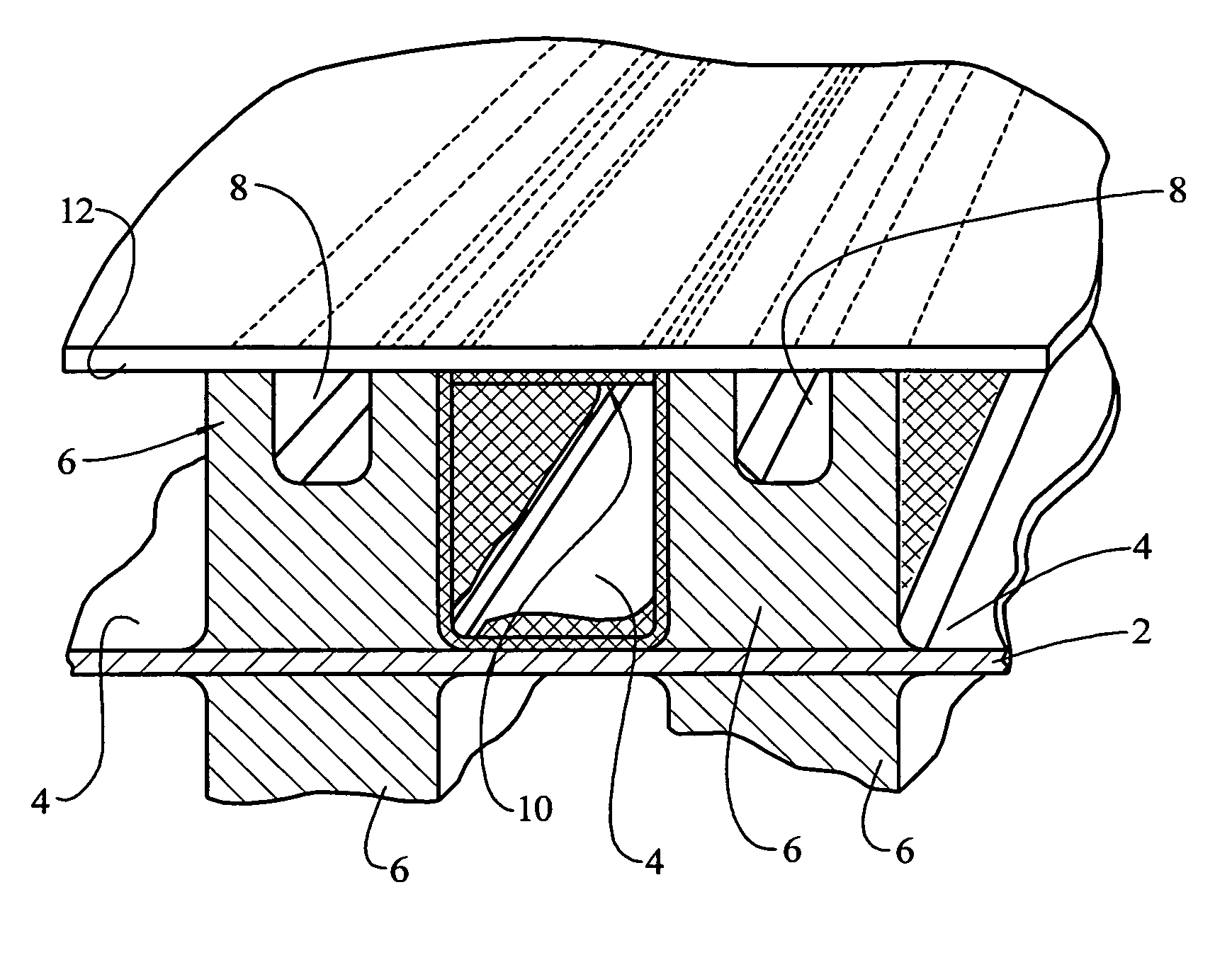
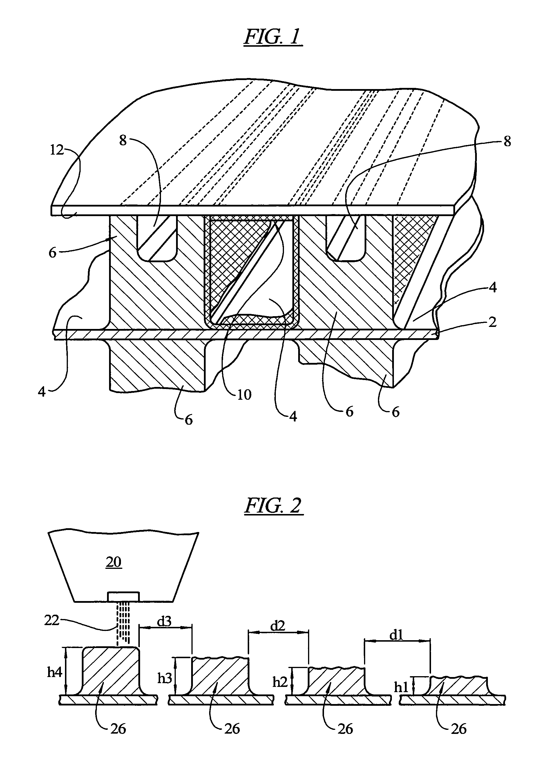
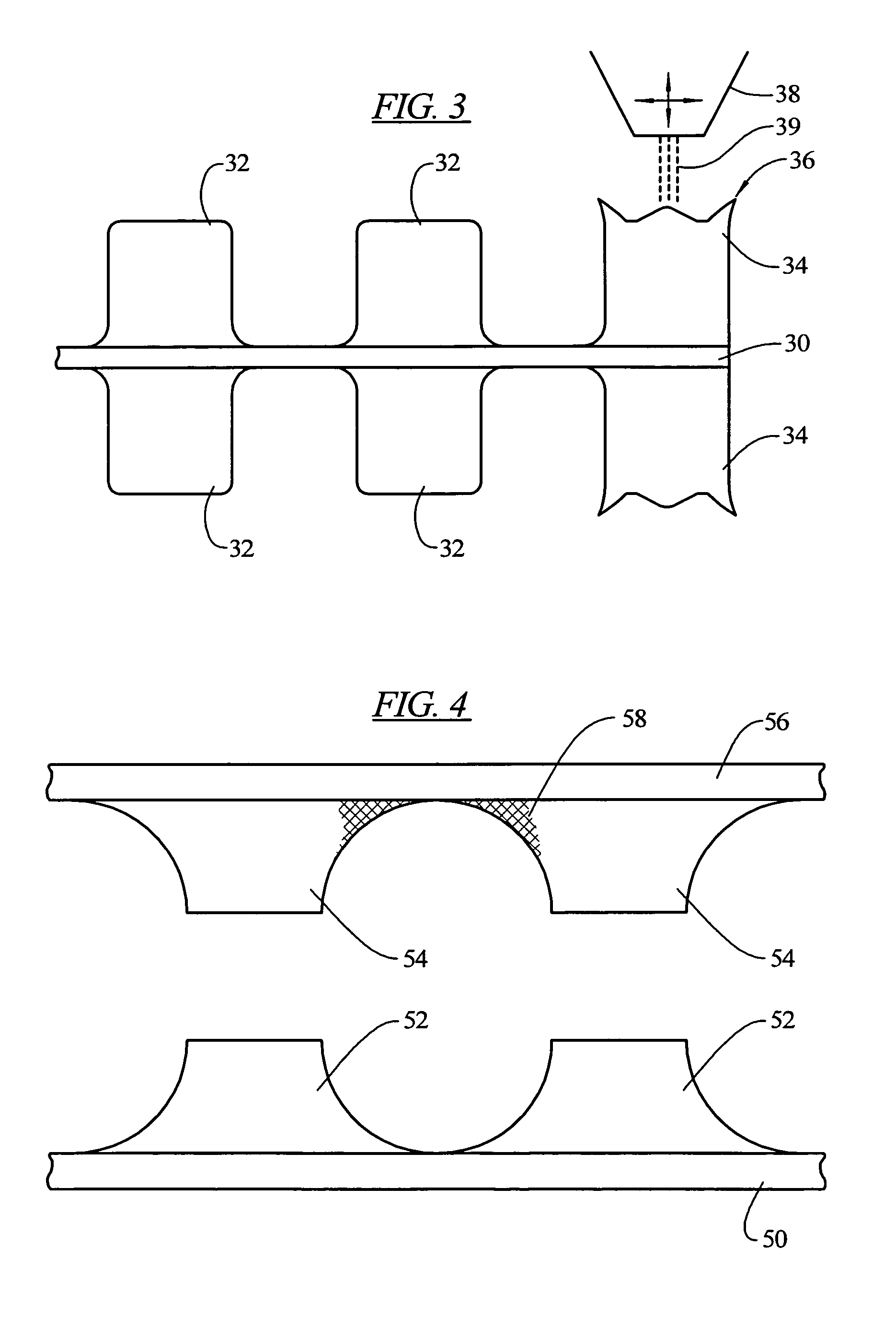
[0027] The present teachings provides new methods, apparatuses and materials to make parts of electrochemical cells, wherein all of the design features are created by depositing materials on a substrate per the design requirements of the desired electrochemical cell. The materials are applied by material deposition technologies such as those employed in the high-speed and specialty printing industries, e.g. ink jet, laser printing, dispersion printing or lithographic printing. For instance, material deposition apparatuses such as those used in the semiconductor industry can be employed. Example apparatuses include printers of the DMP-2800 (DIMATIX, Santa Clara, Calif.) series, a family of ink jet printing systems capable of depositing materials on a variety of rigid and flexible substrates such as plastic, metal and paper with printing feature sizes or line widths as small as 50 μm.

[0028] The deposition of materials can also be carried out via ultra-small orifice deposition apparat...


PUM

PropertyMeasurementUnit
compositionaaaaaaaaaa
conductiveaaaaaaaaaa
electricallyaaaaaaaaaa

Abstract

The present invention relates to the resultant products, the method and apparatus to produce electrochemical cell parts using a material deposition process or processes and specially developed inks appropriate to the specific application requirements at each location on the bipolar plate and can include the gas diffusion layer and the specific deposition of the catalyst and the seals.

Description

INTRODUCTION [0001] In an exemplary application, electrochemical cells such as fuel cells are currently under development to produce electrical power for a variety of stationary and transportation applications. To produce useful currents and voltages, individual fuel cells can be connected in series to form stacks of cells. Adjacent cells in a stack are typically separated by monopolar or bipolar cell plates, where bipolar plates serve as the anode for one fuel cell and the cathode for the adjacent cell. Thus the bipolar plate typically functions as a current collector as well as a barrier between the oxidizers and fuels on either side of the plate. In addition, many stack designs incorporate gas or liquid flow channels into the cell plate. In fuel cells featuring an electrolyte, such as a catalyzed proton exchange membrane (“PEM”) fuel cells, alkaline fuel cells (“AFC”), molten carbonate fuel cells (“MCFC”), solid oxide fuel cells (“SOFC”), direct methanol fuel cells (“DMFC”) and r...

Claims


Application Information

Patent Timeline
Patent Type & Authority Applications(United States)
IPC IPC(8): B05D5/12B01J21/18
CPCH01M4/8605Y10T29/49115H01M4/8807H01M4/881H01M4/8814H01M4/8828H01M4/90H01M4/92H01M8/0228H01M8/0271H01M8/1011H01M2008/1095Y02E60/523Y02E60/50H01M4/8657Y02P70/50
Inventor BUCKLEY, DANIEL T.
Owner AMERICAN GFM
Why Eureka
Try Eureka