Precision roll turning lathe

a technology of precision rolling guide and rolling guide, which is applied in the direction of manufacturing tools, propelling pencils, tool holders, etc., can solve the problems of high-speed carriage, insufficient cutting speed, and inability to afford a cutting speed sufficient to provide high-precision machined surfaces, so as to prevent the lowering of machining precision and reduce the generation of heat in the guide surface of the z-axis rolling guide.

Active Publication Date: 2007-11-01
TOSHIBA MASCH CO LTD
View PDF52 Cites 35 Cited by
  • Summary
  • Abstract
  • Description
  • Claims
  • Application Information

AI Technical Summary

Benefits of technology

[0015] According to the present invention, by selectively using the tool post and the fly cutter spindle device, both mounted on the tool swivel, it becomes possible to carry out high-precision machining on a roll-shaped workpiece not only to produce transverse grooves (circumferential grooves) but to produce longitudinal grooves (axial grooves) as well.
[0016] When longitudinal grooves are machined with a machine that employs a rolling guide for guide of the carriage, Z-axis feeding of the carriage can be performed at a relatively low speed, whereby generation of heat in the guide surface of the Z-axis rolling guide can be reduced. This makes it possible to prevent the lowering of machining precision due to thermal deformation of the bed or the saddle while making use of the kinematic performance of the rolling guide.

Problems solved by technology

Such machining involves the problem of insufficient cutting speed.
Thus, a high-speed carriage, even when moved at the highest speed, will fail to afford a cutting speed enough to provide a high-precision machined surface, in particular such an ultraprecision machined surface as required for a mold for molding a lens sheet.

Method used


Image

  • Precision roll turning lathe
  • Precision roll turning lathe
  • Precision roll turning lathe

Examples


Embodiment Construction

[0023] Preferred embodiments of the present invention will now be described with reference to the drawings.

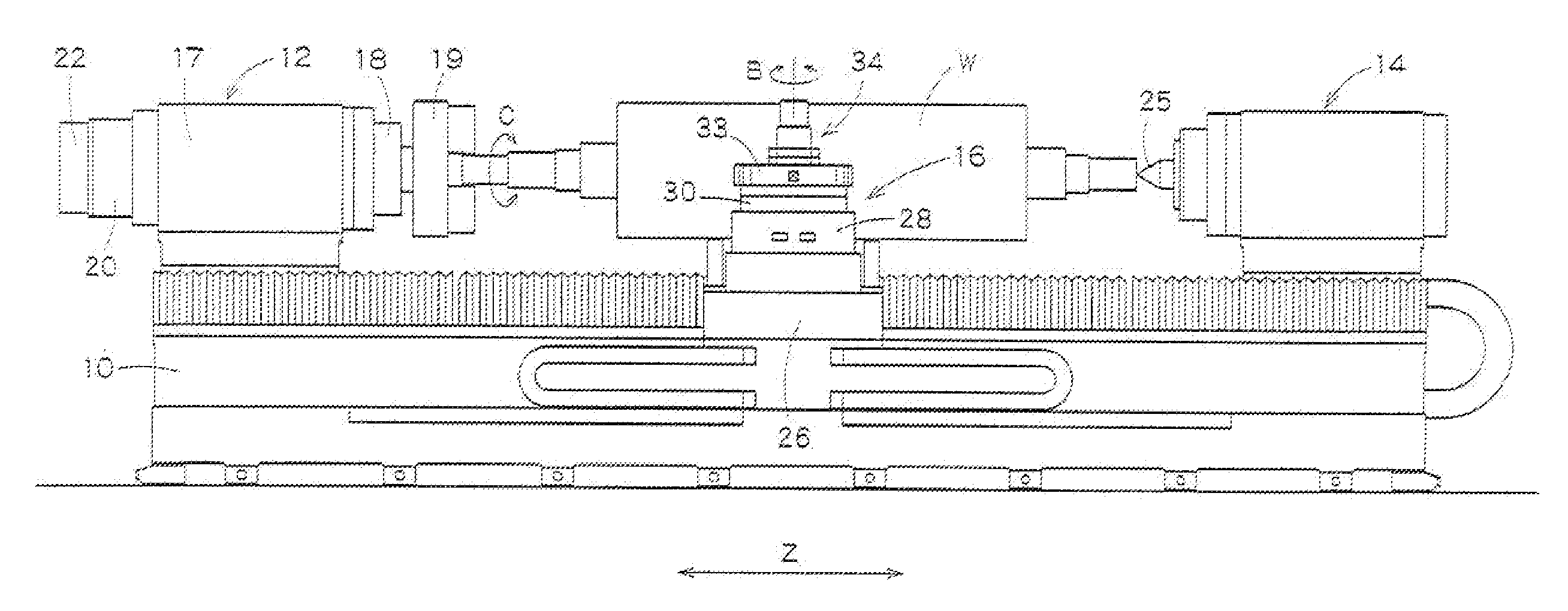
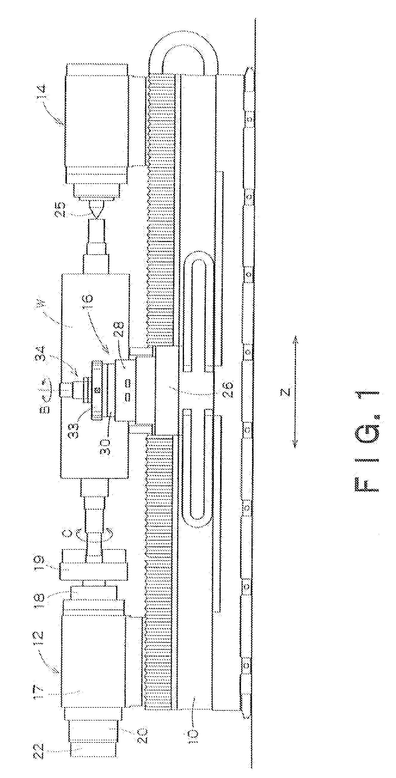
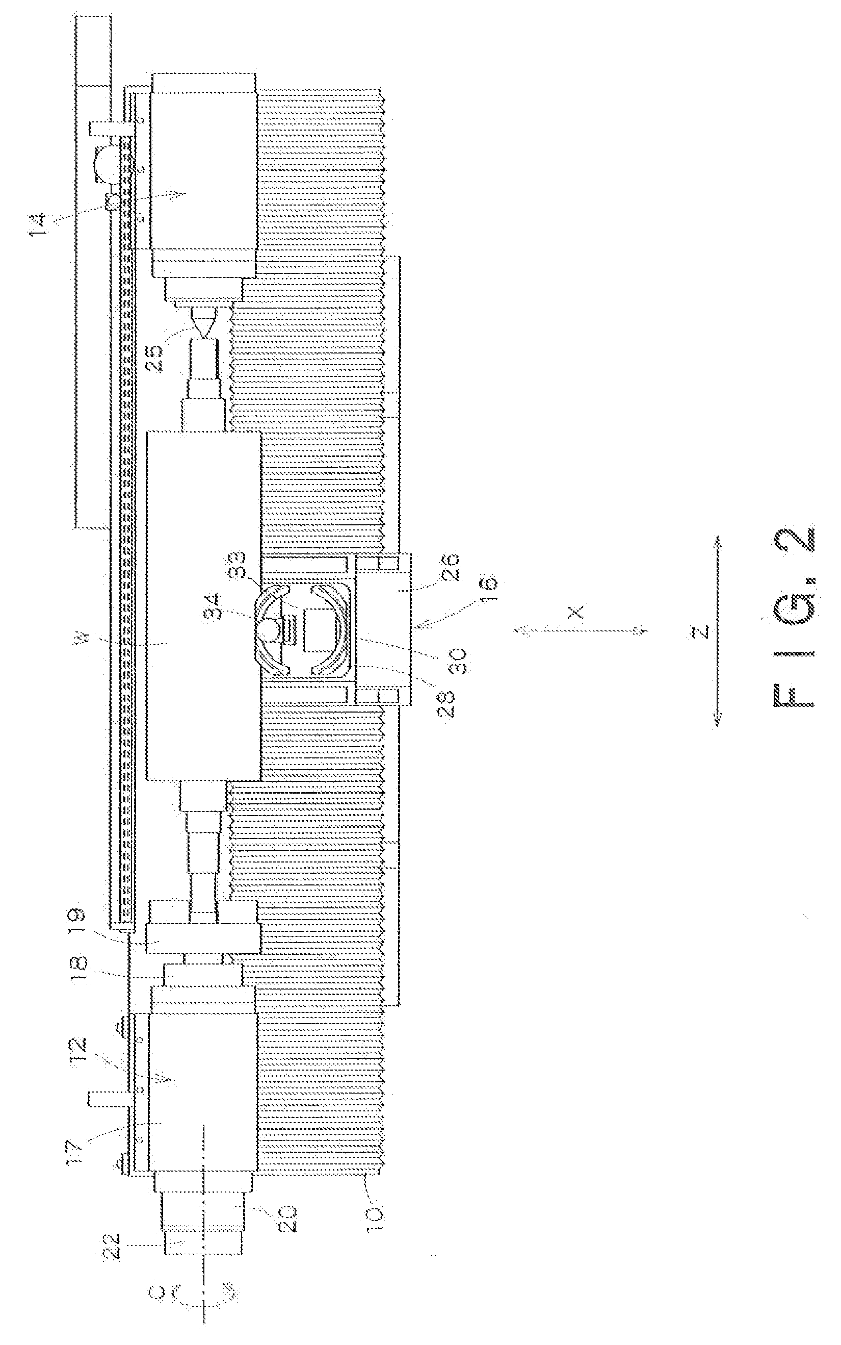
[0024]FIG. 1 is a side view of a precision roll turning lathe according to the present invention, and FIG. 2 is a plan view of the precision roll turning lathe.

[0025] In FIGS. 1 and 2, reference numeral 10 denotes a bed. On the bed 10 are mounted a headstock 12, a tail stock 14 and a carriage 16. A rolled-shaped workpiece W is rotatably supported by the headstock 12 and the tail stock 14.

[0026] The headstock 12 is disposed on one longitudinal end of the bed 10. The headstock 12 includes a body 17, a main spindle 18, a chuck 19 secured to the front end of the main spindle 18, and a servo motor 20 for driving the main spindle 18. The main spindle 18 is supported by a not-shown hydrostatic bearing provided within the body 17. The chuck 19 clamps a spindle of the workpiece W and transmits the rotation of the main spindle 19 to the workpiece W. In the headstock 12, the servo moto...


PUM

PropertyMeasurementUnit
cutting speedaaaaaaaaaa
heightaaaaaaaaaa

Abstract

There is provided a precision roll turning lathe which can not only machine with high precision circumferential transverse grooves in the peripheral surface of a roll but can also machine with high precision longitudinal grooves in the peripheral surface. The precision roll turning lathe includes: a bed 10; a headstock 12, mounted on the bed 10, for rotating a roll-shaped workpiece while holding one end of the workpiece by means of a chuck, said headstock having an indexing axis (C axis) for performing circumferential indexing of the workpiece; a tail stock 14, mounted on the bed 10 and disposed opposite the headstock 12, for rotatably supporting the other end of the workpiece; a carriage 16 including a saddle 26 mounted on the bed 10 movably in the longitudinal direction (Z-axis direction) of the workpiece, and a table 28 mounted on the saddle 26 movably in a direction (X-axis direction) perpendicular to the longitudinal direction of the workpiece; a tool swivel 30 mounted on the table 28 and having an indexing axis (B axis); a tool post 33 mounted on the tool swivel 30 and having a plurality of cutting tools 36 attached thereto; and a fly cutter spindle device 34 mounted to the tool post 34 and having a cutter spindle for rotating a fly cutter 39.

Description

BACKGROUND OF THE INVENTION [0001] 1. Field of the Invention [0002] The present invention relates to a precision lathe for carrying out machining of grooves on a roll, and more particularly to a precision roll turning lathe which can not only machine circumferential grooves in the peripheral surface of a roll but can also machine axial grooves in the roll surface with high precision. [0003] 2. Background Art [0004] Roll grinders and roll turning lathes are generally used as machine tools for machining rolls. A roll grinder includes a headstock, a tail stock, and a carriage which is provided with a grinding wheel. [0005] Such a roll grinder can carry out grinding with a grinding wheel of the peripheral surface of a roll and, in addition, machining of grooves in the peripheral surface. Japanese Patent Laid-Open Publication No. 2003-94239 describes a roll grinder which is provided, in its carriage, with a groove-machining device having a cutting saw blade for groove cutting. [0006] A r...

Claims


Application Information

Patent Timeline
Patent Type & Authority Applications(United States)
IPC IPC(8): B23B27/00
CPCB23B3/162B23B5/08B23B29/244B23B2220/12B23B2226/31B23B2250/04Y10T82/2587Y10T29/5155Y10T29/5174Y10T82/16131Y10T82/2524Y10T82/2508B23C3/30B43K21/02B43K24/06B43K24/08
Inventor AKIYAMA, TAKANOBU
Owner TOSHIBA MASCH CO LTD
Why Eureka
Try Eureka