Charging circuit
a charging circuit and circuit technology, applied in the direction of excess voltage responsive arrangements, emergency protective arrangements for limiting excess voltage/current, transportation and packaging, etc., can solve the problems of affecting charging operation, extremely high voltage supplied from the ac adaptor to the electronic equipment or other power supply circuit, and the inability of the electronic circuit to perform normal functions
- Summary
- Abstract
- Description
- Claims
- Application Information
AI Technical Summary
Benefits of technology
Problems solved by technology
Method used
Image
Examples
first embodiment
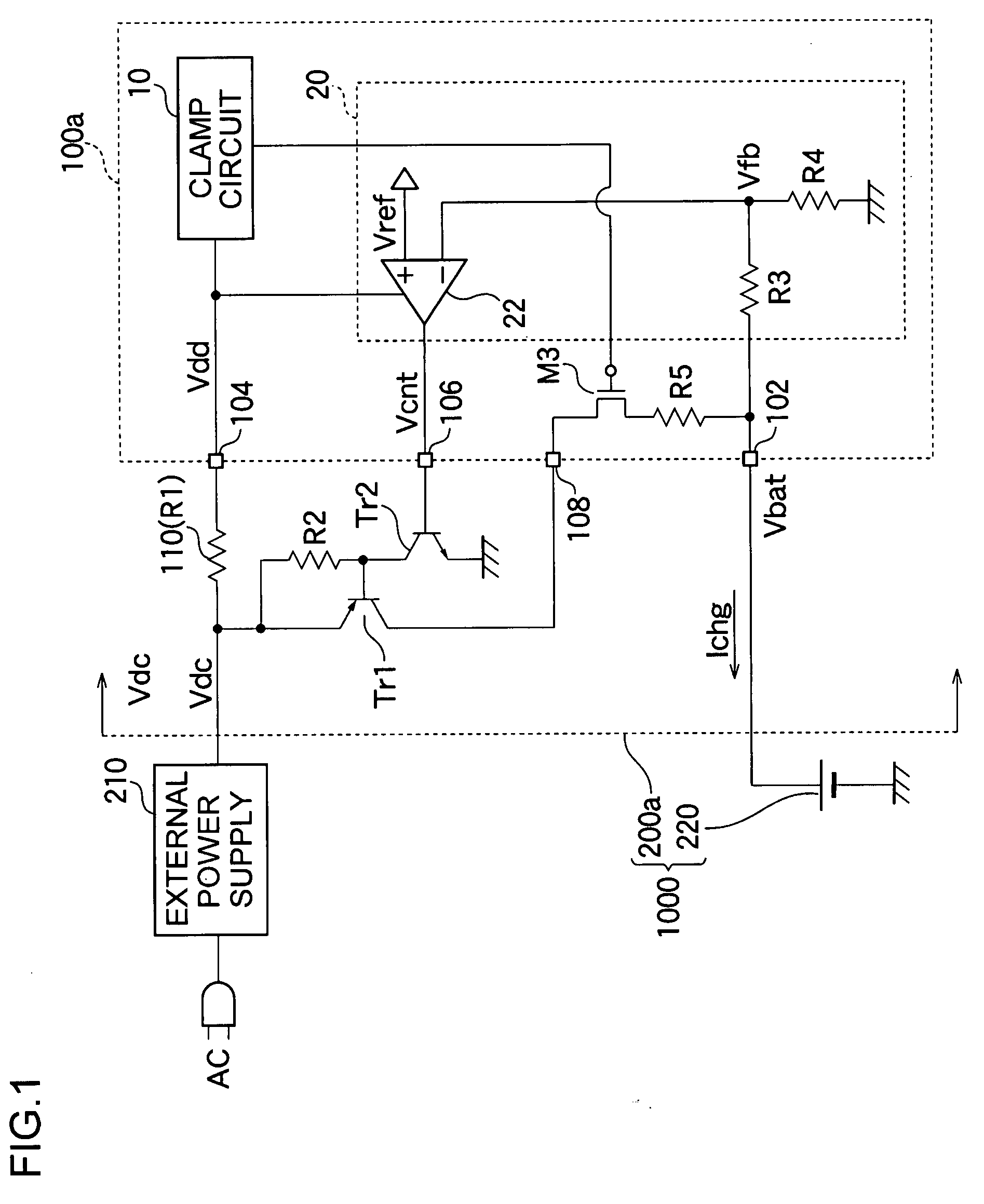
[0047]FIG. 1 is a circuit diagram showing an entire configuration of a charging circuit 200a according to a first embodiment and an electronic equipment 1000.
[0048]The electronic equipment 1000 is a battery-driven portable information terminal such as a portable telephone terminal, PDA, and a notebook PC. The electronic equipment 1000 includes the charging circuit 200a and a battery 220. The electronic equipment 1000 also includes a power supply circuit (not shown), DSP, a liquid crystal panel, and other analog and digital circuits.
[0049]The battery 220 is a secondary battery such as a lithium-ion battery and a NiCd (nickel-cadmium) battery, and a battery voltage Vbat of the battery 220 is supplied to other circuit blocks of the electronic equipment 1000.
[0050]An external power supply 210 is an AC adaptor which converts a commercial alternating voltage into a DC (direct-current) voltage or a DC / DC converter which steps down a voltage of an in-vehicle battery. The external power supp...
second embodiment
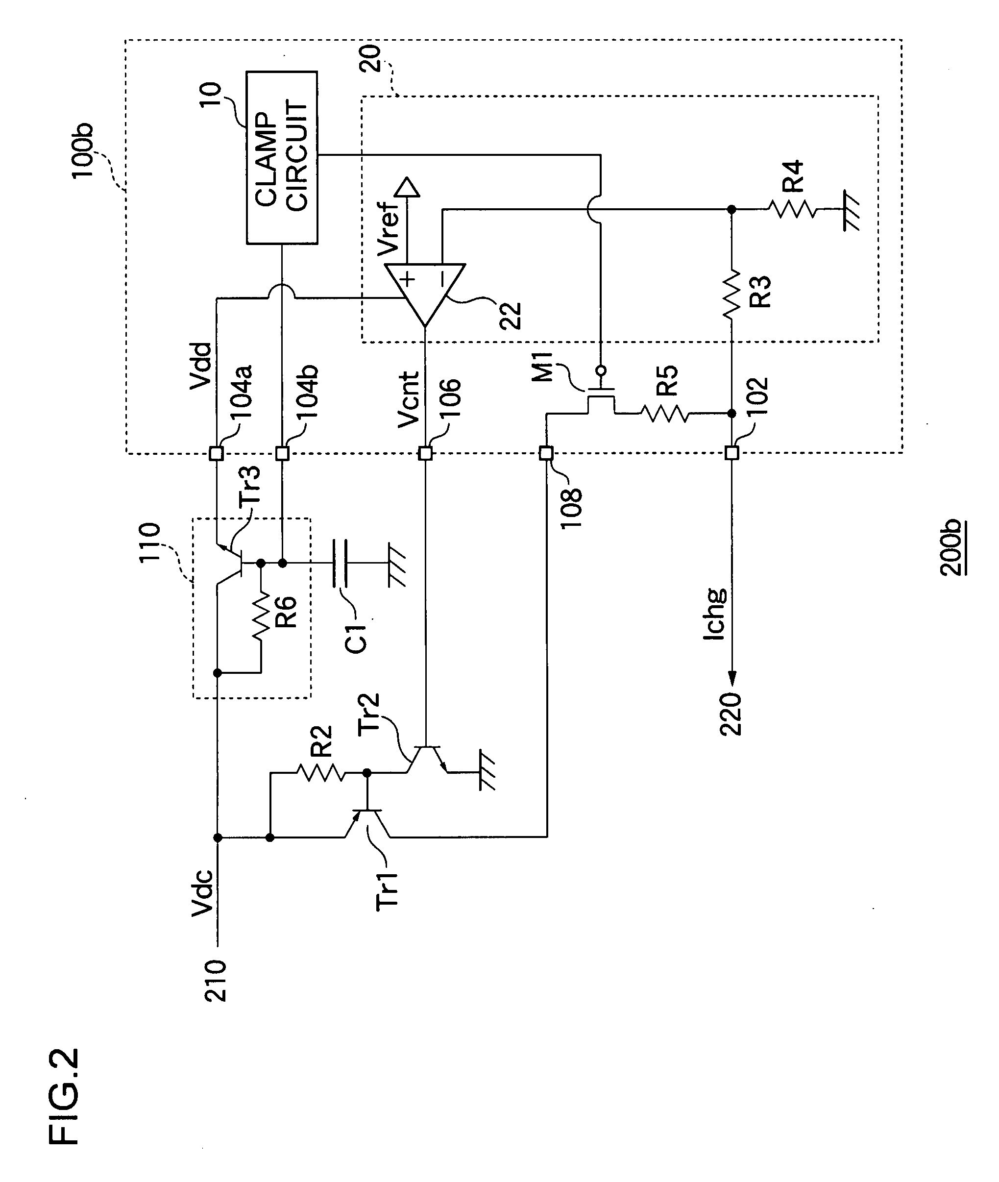
[0067]FIG. 2 is a circuit diagram showing a configuration of a charging circuit 200b according to a second embodiment. The difference between the second embodiment and the first embodiment will mainly be described.
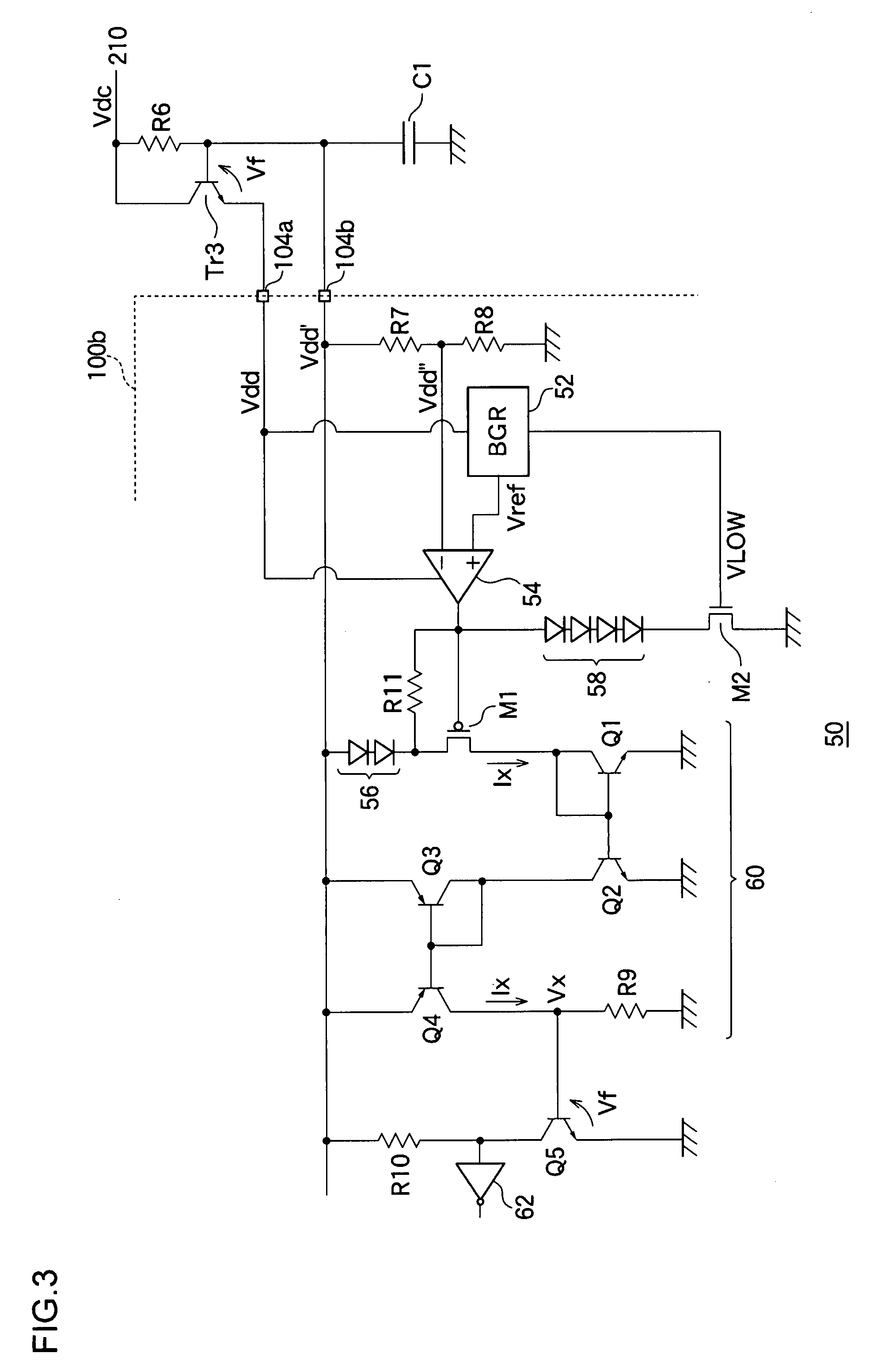
[0068]In the charging circuit 200a of FIG. 1, a resistor element is used as the voltage adjusting circuit 110. Consequently, sometimes power consumption is increased at the voltage control resistor R1 in applying the overvoltage. For example, in the case of the external power supply voltage Vdc=30V and the clamp voltage Vclmp=7, the voltage drop of 23V is generated. When the resistance value is set to 100Ω, the power consumption of about 232 / 100≈5 W is generated. Accordingly, it is necessary that the element having the rated electric power of at least 5 W be selected as the voltage control resistor R1. From the viewpoints of size and cost of component, sometimes it is necessary to avoid the use of the resistor element having the large rated electric power. The charging cir...
PUM
 Abstract
Description
Claims
Application Information
 - R&D
- Intellectual Property
- Life Sciences
- Materials
- Tech Scout
- Unparalleled Data Quality
- Higher Quality Content
- 60% Fewer Hallucinations
Browse by: Latest US Patents, China's latest patents, Technical Efficacy Thesaurus, Application Domain, Technology Topic, Popular Technical Reports.
© 2025 PatSnap. All rights reserved.Legal|Privacy policy|Modern Slavery Act Transparency Statement|Sitemap|About US| Contact US: help@patsnap.com


