[0014] These and other features and advantages of the present invention will be apparent from the following detailed description, in conjunction with the appended claims.
[0015] The benefits and advantages of the present invention will become more readily apparent to those of ordinary skill in the relevant art after reviewing the following detailed description and accompanying drawings, wherein:
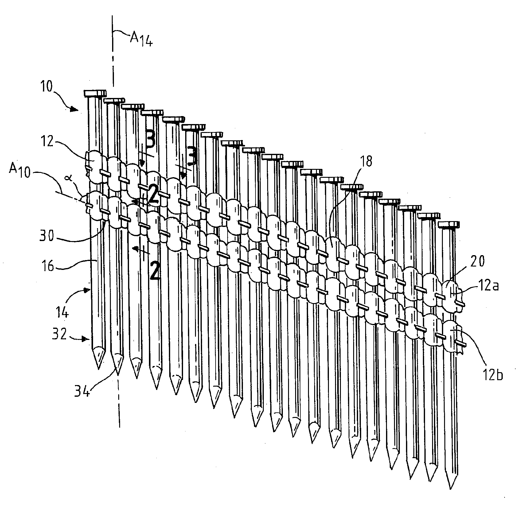
[0016]FIG. 1 is a plan view of one embodiment of a nail strip or
collation having a pair of plastic molded carrier strips;
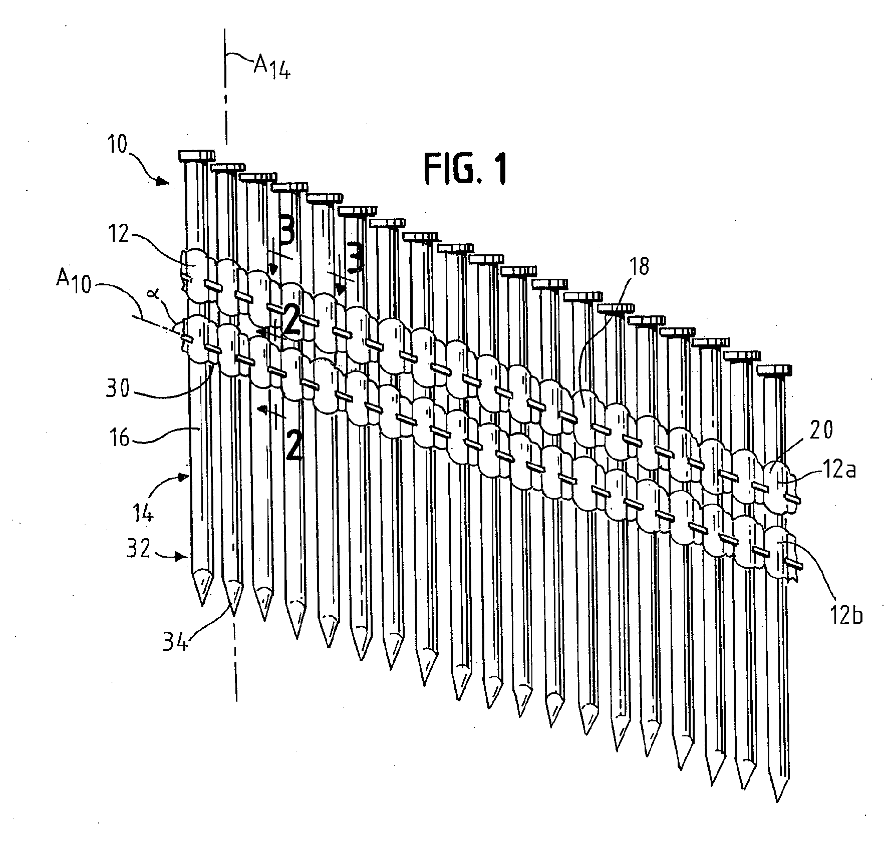
[0017]FIG. 2 is a cross-sectional view taken along line 2-2 of FIG. 1;
[0018]FIG. 3 is a cross-sectional view taken along line 3-3 of FIG. 1;
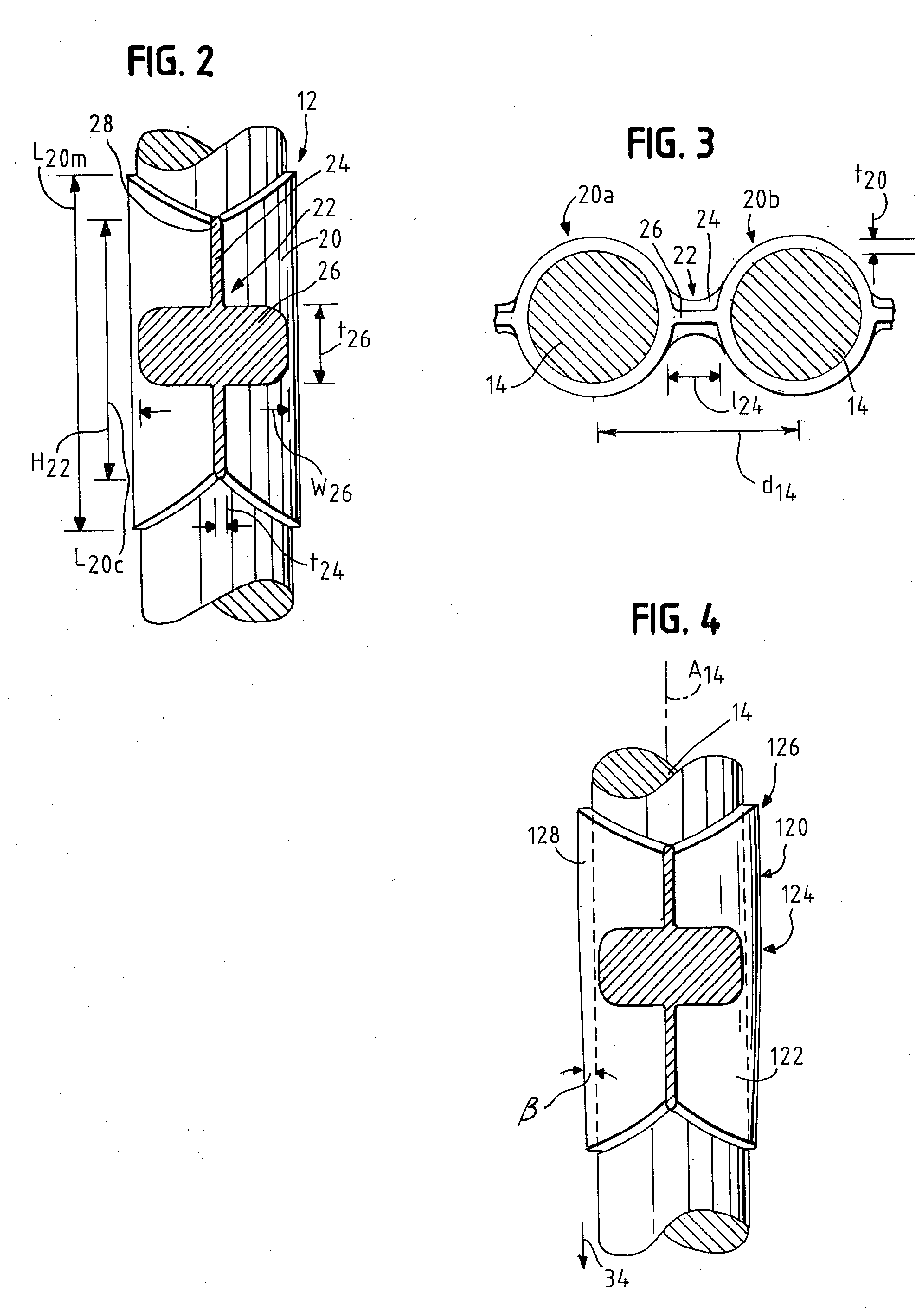
[0019]FIG. 4 is an illustration similar to FIG. 2, showing a tapered collar;
[0020]FIGS. 5A and 5B illustrate portions of strips having angled ribs; and
[0021]FIGS. 6 and 6A illustrate an alternate bridge portion that is embossed, in which FIG. 6A is a cross-section taken along line 6A-6A of FIG. 6.
[0025] As will be appreciated by those skilled in the art, the illustrated nails 14 are full head nails, rather than D-head (or clipped head) nails. Accordingly, the nails 14 provide increased holding characteristics (due to the increased surface area of the nail head H). However, it will also be appreciated that using full head H nails 14 requires that the strip 10 is fabricated with a slightly greater distance d14 between the (axes A14 of the) nails 14 to accommodate the larger nail heads H.
[0022] While the present invention is susceptible of embodiment in various forms, there is shown in the drawings and will hereinafter be described a presently preferred embodiment with the understanding that the present disclosure is to be considered an exemplification of the invention and is not intended to limit the invention to the specific embodiment illustrated.
[0023] It should be further understood that the title of this section of this specification, namely, “Detailed Description Of The Invention”, relates to a requirement of the United States Patent Office, and does not imply, nor should be inferred to limit the
subject matter disclosed herein.
[0024] Referring now to the figures and in particular to FIG. 1 there is shown a nail strip 10 having a plastic
collation system 12 embodying the principles of the present invention. In the illustrated strip 10, the nails 14 are positioned at an angle a of about 20 degrees to the transverse direction of the strip 10; however, other angles a (including zero degrees) are contemplated for use with the present invention.
[0025] As will be appreciated by those skilled in the art, the illustrated nails 14 are full head nails, rather than D-head (or clipped head) nails. Accordingly, the nails 14 provide increased holding characteristics (due to the increased surface area of the nail head H). However, it will also be appreciated that using full head H nails 14 requires that the strip 10 is fabricated with a slightly greater distance d14 between the (axes A14 of the) nails 14 to accommodate the larger nail heads H.
[0026] The nails 14 are collated and held to one another by the plastic collation 12. The plastic collation 12 is molded to, over and around the shanks 16 of the nails 14, and connects each nail 14 to its adjacent nail or nails (that is, extends between the nails 14). The collation 12 is formed as a contiguous molding (as indicated generally at 18) around and between the nails 14; nevertheless, for purposes of this disclosure, the molding 18 is viewed as having a collar portion 20, which is that portion that encircles the nail shank 16, and a connecting portion 22, which is that portion that extends between and connects adjacent collar portions 20. In the nail strip 10 illustrated in FIG. 1, two plastic moldings or collations are shown, namely an upper molding or collation 12a and a lower molding or collation 12b, that are formed with structure similar to one another. The following disclosure is applicable for both of the moldings and are referred to collectively as molding or collation 12.
[0027] The present nail collation 12 differs from previously known plastic collations in a number of important aspects. First, rather than the plastic merely encircling and extending around and between the nails, the present collation uses a material that is molded and adheres to the nails 14. It has been found that plastic that is adhered to the nails, rather than merely molded around the nails is advantageous in that the plastic material tends to remain on the nail shank 16 during driving. That is, the collation 12 material is maintained on the shank 16 as the nail 14 penetrates the substrate and thus enters the substrate with the nail 14. Advantageously, much less debris is generated during driving of a nail 14 from the present nail strip 10 compared to prior known nail strips.
[0028] It will also be appreciated that the adhesion of the plastic material to the nails 14 also has benefits vis-à-vis the rigidity of the nail strip 10. That is, when the plastic merely encircles the nail shanks, the plastic can slip around the nail shanks. On the other hand, by adhering the
plastic molding 12 to the shanks 16, the nail strip 10 tends to become more rigid and is less likely to flex and to corrugate.
[0029] The material is an
adhesive polymer, an
epoxy or the like. The material can be, for example, an
adhesive polyolefin such as a
maleic anhydride modified
polyolefin, such as
polypropylene,
polyethylene or the like. The material can include a blend of a
polyolefin and a modified polyolefin, such as a blend of
polypropylene and a
maleic anhydride modified
polypropylene. One or more other resins can also be used, such as a
polyvinyl alcohol (PVA) based material, an
ethylene vinyl alcohol (EVA) based material, an
acrylonitrile butadiene
styrene (ABS) based material, ionomers, methyl methacrylates and the like. Fillers can also be used as can blends of any of the materials, as suitable. Other materials will be recognized by those skilled in the art and are within the scope and spirit of the present invention.
[0030] A present plastic composition is a polypropylene resin that has been modified to enhance adhesion to surfaces, including
metal surfaces. A preferred resin is a
maleic anhydride modified polypropylene commercially available from Mitsui Chemicals America, Inc, of Rye Brook, N.Y., under the tradename ADMER® QF5512A.
[0032] In Table 1, the plastic adhesion
shear strength (in pounds, lbs.) was measured using a
tensile testing device, by forcing the nails through a precisely sized hole in a direction parallel to the nail axis A14 and measuring the force required to separate the nail 14 from the plastic 12. The nails that were pre-heated prior to molding were heated to a temperature of about 500° F. to 550° F., after which the plastic was molded to the nails. For the post heat treatment, the nails were heated to the temperature shown for a period of about 30 minutes.
[0033] As can be seen from Table 1, the difference in plastic
shear strength between the non-pre-heated nails and the preheated nails is quite significant. For the present maleic anhydride modified polypropylene, the difference is a factor of over 15 (71.0 lbs. / 4.6 lbs.) without post molding heat treatment. With post molding heat treatment, the shear strength increased by a factor of almost 3 over the nonpost
heat treated (pre-heated) nails. The plastic shear strength was shown to be about 71.0 lbs with proheating the nails prior to molding the plastic to the nails. In no case did a cold-applied plastic approach the shear strength of the pre-heated nail strips.
[0034] It was observed that nails strips formed in accordance with the present invention exhibited a very limited amount of debris compared to known plastic collations, principally because the plastic remained on the nail shank and penetrated the substrate (wood) with the nail. Moreover, it was found that the debris that was generated was in the form of a finer material (smaller sized particles) so there was less of a
housekeeping issue with the debris that was generated.
[0035] Debris was collected from samples of nails to determine the “debris performance”, or reduction of debris generation of the present collation
system. The amount of loose debris was measured by first weighing a given collated nail strip consisting of 10 nails. The starting weight of plastic was calculated by subtracting the weight of 10 uncollated nails from this amount. The test nail strip was then fired into a substrate (e.g., wood board) surrounded by an
enclosure to facilitate the capture and collection of the loose debris. The collected loose debris was then weighed and divided by the original starting plastic amount to yield the percent loose debris for a particular plastic collation material.
[0036] Table 2, below, summarizes the results obtained with selected three of collating
plastic materials (a non-adhesive polypropylene material, an adhesive material in accordance with the present invention that was formulated as a blend of 50 percent by weight polypropylene and 50 percent by weight of the maleic anhydride modified polypropylene, and a formulation of 100 percent of the maleic anhydride modified polypropylene). Firing tests were conducted in both pine and
medium density fibreboard (MDF) substrates. TABLE 2DEBRIS GENERATED FROM VARIOUSPLASTIC NAIL COLLATIONS% Loose Debris% Loose DebrisPlastic collating material(Pine)(MDF)Non-adhesive polypropylene8691
Polypropylene / maleic anhydride1714modified polypropylene blend(50% / 50% by weight)100% maleic anhydride modified00polypropylene,
[0037] It was also found that the nails carried the plastic into the wood and that the plastic was embedded in the wood with the nail. In fact, surprisingly, this increased the nails' holding power in the wood. It is believed that this was due to the adhesive nature of the plastic as it embedded in the wood, in conjunction with the adhesion of the plastic to the nail. That is, it is believed that the plastic (adhesive) flowed into the wood structure and bonded with the wood structure, thus providing even greater holding power.
[0038] Table 3 below shows the results of evaluations that were conducted to compare the holding power or withdrawal strength of nails that were “fired” into wood from nail strips in accordance with the present invention to non-pre-heated polypropylene or control molded nail strip collations. The withdrawal strengths were measured as the force (in lbs / in of withdrawal) required to pull the nail from the wood. The values were normalized (e.g. calculated per inch of withdrawal) by dividing the force by the
penetration depth. TABLE 3PENETRATION AND WITHDRAWAL STRENGTH OF NAILSCARRIED IN VARIOUS PLASTIC NAIL COLLATIONSWithdrawalStrengthPlasticSampleStandingPenetrationUltimate(lbs. / in. ofCollationNo.Ht. (in)(in)(lbs)withdrawal)Material10.2582.432408.73168.06Tymor ™20.5852.415372.28154.14Tymor ™30.6182.382150.0663.00Control40.6162.384150.9363.31Control50.6212.379231.8697.46Admer ®60.6442.356127.8754.27Control
[0039] As can be seen from the data of Table 3, nail strips in accordance with the present invention exhibited considerably higher withdrawal strengths compared to non-adhered (control) nails. The control nails exhibited withdrawal strengths of about 54.3 to 63.3 lbs, whereas the preheated nails exhibited withdrawal strengths of about 97.5 to 168.1 lbs. In each case, the pre-heated nails required almost 54 percent greater force to withdraw or pull out the nails. At the same time, the
nail penetration was essentially equal to that of the non-preheated nails. The Admer® and Tymor™ materials are both maleic anhydride modified polypropylene.
[0040] In the present nail strips 10, the plastic is a uniform material that is molded over the nail shanks 16 and between the nails 14. It will be appreciated that the plastic material can be a multipart molding, in which discrete
layers in the molding (collating) material are provided on the nails. In such a system, an adhesive can be applied or bonded to the nails onto which a layer of a material with desired characteristics (e.g., a stiffer or more rigid material or a more
impact resistant material) is applied. Alternately, of course, a layered configuration can be achieved using a coextrusion of two or more plastics.
[0041] Another aspect of the present nail strip 10 is the shape or configuration of the molding around and between the nails 14. That is, the shape of the collars 20 and the connecting portions 22. In a present strip 10, the collars 20 are formed as encircling elements that have a greater longitudinal or
axial length at about a midpoint L20M between the connecting elements 22 (that is at about the midpoint of the circle inscribed by the nail), and dip to a smaller
axial length at about the connecting portions L20C.
[0042] The connecting portions 22 include a bridge 24 that extends from one collar 20a to the adjacent collar 20b and is about the height H22 of the collar 20 at the collar 20 / connecting portion 22 juncture. The bridge 24 is a relatively long, thin element that in fact “bridges” the two adjacent collars 20a, 20b. A rib 26 runs along the bridge 24 from one collar 20a to the next 20b. The rib 26 is a cross-piece to the bridge 24 and has a low profile (e.g., is short) in the nail axial direction or along the length of the nail (i.e., has a low thickness t26), but has a greater depth or width w26 than the bridge 24. As seen in FIGS. 2 and 3, the cross-section of the bridge 24 and rib 26 is
cruciform-shaped, and with the 26 rib serving as the cross-piece, the rib 26 resides at about the middle of the bridge 24. A cross-section taken through the nails 14 (see, FIG. 3) that provides a top or bottom view of the connecting portion 22 shows that the rib 26 actually has a concave shape as it extends between the nails 14. Both the bridge 24 and the rib 26 are formed having rounded ends, as indicated at 28.
[0043] As will be appreciated by those skilled in the art, when a nail 14 is driven from the strip 10, it is the nail 14, the collar 20 and the connecting portion 22 between the driven nail 14 and the next adjacent nail 14b (see right-hand side of FIG. 1) that are separated from the strip 10. Desirably, this entire “assembly” is driven into the substrate, and it will be understood that it is desirable to drive as much of the assembly as possible into the wood to, among other things, reduce the amount of debris that is generated.
[0044] To effect separation of the connecting portion 22, a notch 30 can be formed at the base or bottom 32 of the connecting portion 22 along a desired line of separation, or at the juncture of the connecting portion and the next adjacent nail. This provides a location at which the nail 14, collar 20 and connecting portion 22, as a unit, separate from the strip 10.
[0045] The connecting portion 22 provides the necessary rigidity to the strip 10 that, in conjunction with the adhesive characteristics of the plastic, prevents corrugation of the strip 10. Nevertheless, even with the increased adhesion and rigidity, that no significant increase in force is needed to drive the nail 14 and separate the nail 14 from the strip 10.
[0046] In a present nail strip 10, the upper and lower collations 12a,b have essentially equal dimensions. The collar 20 has a length L20M, L20C of about 0.360 inches to 0.480 inches and a thickness t20 of about 0.005 inches to 0.015. The bridge 24 has a length I24 of about 0.280 inches to 0.420 inches and a thickness t24 of about 0.006 inches to 0.014 inches and the rib 26 has a thickness t26 of about 0.045 inches to 0.060 inches and a width w26 of about 0.087 inches to 0.128 inches. It will be appreciated that because the rib 26 has a concave shape, the width w26 varies along the length of the rib 26.
[0047] Referring to FIG. 4, the collar 120 can be formed having a taper or a thinned region 122 at the collar portion 124 closest to the tip 34 of the nail 14 or at the leading end of the collar 120. The collar 120 expands or thickens toward the trailing end 126. It has been observed that this taper 122 facilitates penetration of the nail 14 and plastic collar portion 120 into the wood. The taper 122 is preferably formed at an angle β relative to the longitudinal axis A14 of the nail 14, of about 0.5 degree to about 5.0 degrees, and most preferably about 1.0 degrees. The taper 122 forms a wedge 128 that assists penetration of the nail 14 into the substrate and can further enhance the withdrawal resistance. It should, however, be recognized that the angle β cannot be too great in that the wedge 128 could serve to split the wood.
[0048] It has also been observed that the location of the collar 20 on the shank 16 contributes to increasing the penetration of the nail 14 into the wood. Specifically, it has been found that positioning the collar 20 closer to the tip 34 of the nail 14 results in increased
nail penetration. It is believed that because the collar 20 (which is an interference to penetration) is positioned closer to the nail tip 34, the greatest interference (that is as the collar 20 is entering the wood) is encountered while the impulse from the nail driving tool is high. Accordingly, the greatest resistance to penetration is overcome while the impulse from the tool is high, and, as such, penetration of the nail is greater when the collar 20 is positioned close to the nail tip 34 rather than farther back on the nail shank 16, near to the nail head H.
[0049] An evaluation of the effect of the collar 20 position on the shank 16 was conducted. Using a nail 14 that was 3 inches long and 0.131 nominal
diameter, with a collar length L20M of 0.5 inches and a thickness t20 of about 0.020 inches and a collation material of maleic anhydride modified polypropylene (Admer®) and a pneumatic driving force of 90 psi, it was found that a nail 14 having a collar 20 positioned 2.25 inches from the tip 34 was driven (had a penetration of) 2.45 inches, a nail 14 having a collar 20 positioned 1.5 inches from the tip 34 was driven 2.75 inches, a nail 14 having a collar 20 positioned 0.5 inches from the tip 34 was driven 2.975 inches, and a bare nail 14 was driven 2.925 inches
[0050] It will be appreciated by those skilled in the art that the use of a forward positioned collar 20 (or more generally a forwardly positioned collation element or support) is not limited to use with a collated nail strip 10. Rather, such an arrangement can be used with other strip formed fasteners and other strip-formed
consumables.
[0051]FIGS. 5A and 5B illustrate an embodiment 210 in which the ribs 226 are formed at an angle γ and γ′ relative to an axis A210 of the strip 10 (as opposed to the ribs 26 in the embodiment of FIG. 1 which are generally parallel to the axis A10).
[0052]FIGS. 6 and 6A illustrate an alternate embodiment of the plastic nail collation 310 in which an embossed pattern 324 is formed in the connecting portion 322 of the strip 310, rather than the bridge 24 and rib 26 configuration (of FIGS. 1-5). In the embossed pattern 324 embodiment, a pattern of ribs 326 is formed in the connecting portion 322 that can extend in one or both directions relative to a plane P322 that is defined by the connecting 322 portion extending between the collars 320 (e.g., into or out of or both into and out of the plane P322 defined by the connecting portion 322 and the adjacent nails 14a,b). A cross-section of a one-directional
embossing 324 is illustrated in FIG. 6A. The
embossing 324 serves to provide a three-dimensional structure, much like the bridges 24 and ribs 26, to enhance the rigidity of the strip 310. In addition, it is anticipated that the
embossing 324 can provide the necessary rigidity and
predictability in separation while at the same time, reducing the amount of material needed to firm the strip 310. A rib 325 can be used with the embossed collation embodiment 310, as well. The embossing can also be formed in the collar. It will be appreciated by those skilled in the art from a review of the drawings that the present collation can be used with coiled nails (e.g., a roller nail strip) as well. In such an arrangement, the collation is formed with a bridge connecting the collar portions, however, a reinforcing or stiffening element (e.g., rib) is not used so that the strip can be coiled.
[0045] The connecting portion 22 provides the necessary rigidity to the strip 10 that, in conjunction with the adhesive characteristics of the plastic, prevents corrugation of the strip 10. Nevertheless, even with the increased adhesion and rigidity, that no significant increase in force is needed to drive the nail 14 and separate the nail 14 from the strip 10.
[0047] Referring to FIG. 4, the collar 120 can be formed having a taper or a thinned region 122 at the collar portion 124 closest to the tip 34 of the nail 14 or at the leading end of the collar 120. The collar 120 expands or thickens toward the trailing end 126. It has been observed that this taper 122 facilitates penetration of the nail 14 and plastic collar portion 120 into the wood. The taper 122 is preferably formed at an angle β relative to the longitudinal axis A14 of the nail 14, of about 0.5 degree to about 5.0 degrees, and most preferably about 1.0 degrees. The taper 122 forms a wedge 128 that assists penetration of the nail 14 into the substrate and can further enhance the withdrawal resistance. It should, however, be recognized that the angle β cannot be too great in that the wedge 128 could serve to split the wood.
[0044] To effect separation of the connecting portion 22, a notch 30 can be formed at the base or bottom 32 of the connecting portion 22 along a desired line of separation, or at the juncture of the connecting portion and the next adjacent nail. This provides a location at which the nail 14, collar 20 and connecting portion 22, as a unit, separate from the strip 10.
[0044] To effect separation of the connecting portion 22, a notch 30 can be formed at the base or bottom 32 of the connecting portion 22 along a desired line of separation, or at the juncture of the connecting portion and the next adjacent nail. This provides a location at which the nail 14, collar 20 and connecting portion 22, as a unit, separate from the strip 10.
[0047] Referring to FIG. 4, the collar 120 can be formed having a taper or a thinned region 122 at the collar portion 124 closest to the tip 34 of the nail 14 or at the leading end of the collar 120. The collar 120 expands or thickens toward the trailing end 126. It has been observed that this taper 122 facilitates penetration of the nail 14 and plastic collar portion 120 into the wood. The taper 122 is preferably formed at an angle β relative to the longitudinal axis A14 of the nail 14, of about 0.5 degree to about 5.0 degrees, and most preferably about 1.0 degrees. The taper 122 forms a wedge 128 that assists penetration of the nail 14 into the substrate and can further enhance the withdrawal resistance. It should, however, be recognized that the angle β cannot be too great in that the wedge 128 could serve to split the wood.
[0047] Referring to FIG. 4, the collar 120 can be formed having a taper or a thinned region 122 at the collar portion 124 closest to the tip 34 of the nail 14 or at the leading end of the collar 120. The collar 120 expands or thickens toward the trailing end 126. It has been observed that this taper 122 facilitates penetration of the nail 14 and plastic collar portion 120 into the wood. The taper 122 is preferably formed at an angle β relative to the longitudinal axis A14 of the nail 14, of about 0.5 degree to about 5.0 degrees, and most preferably about 1.0 degrees. The taper 122 forms a wedge 128 that assists penetration of the nail 14 into the substrate and can further enhance the withdrawal resistance. It should, however, be recognized that the angle β cannot be too great in that the wedge 128 could serve to split the wood.
[0041] Another aspect of the present nail strip 10 is the shape or configuration of the molding around and between the nails 14. That is, the shape of the collars 20 and the connecting portions 22. In a present strip 10, the collars 20 are formed as encircling elements that have a greater longitudinal or
axial length at about a midpoint L20M between the connecting elements 22 (that is at about the midpoint of the circle inscribed by the nail), and dip to a smaller axial length at about the connecting portions L20C.
[0046] In a present nail strip 10, the upper and lower collations 12a,b have essentially equal dimensions. The collar 20 has a length L20M, L20C of about 0.360 inches to 0.480 inches and a thickness t20 of about 0.005 inches to 0.015. The bridge 24 has a length I24 of about 0.280 inches to 0.420 inches and a thickness t24 of about 0.006 inches to 0.014 inches and the rib 26 has a thickness t26 of about 0.045 inches to 0.060 inches and a width w26 of about 0.087 inches to 0.128 inches. It will be appreciated that because the rib 26 has a concave shape, the width w26 varies along the length of the rib 26.
[0047] Referring to FIG. 4, the collar 120 can be formed having a taper or a thinned region 122 at the collar portion 124 closest to the tip 34 of the nail 14 or at the leading end of the collar 120. The collar 120 expands or thickens toward the trailing end 126. It has been observed that this taper 122 facilitates penetration of the nail 14 and plastic collar portion 120 into the wood. The taper 122 is preferably formed at an angle β relative to the longitudinal axis A14 of the nail 14, of about 0.5 degree to about 5.0 degrees, and most preferably about 1.0 degrees. The taper 122 forms a wedge 128 that assists penetration of the nail 14 into the substrate and can further enhance the withdrawal resistance. It should, however, be recognized that the angle β cannot be too great in that the wedge 128 could serve to split the wood.
[0047] Referring to FIG. 4, the collar 120 can be formed having a taper or a thinned region 122 at the collar portion 124 closest to the tip 34 of the nail 14 or at the leading end of the collar 120. The collar 120 expands or thickens toward the trailing end 126. It has been observed that this taper 122 facilitates penetration of the nail 14 and plastic collar portion 120 into the wood. The taper 122 is preferably formed at an angle β relative to the longitudinal axis A14 of the nail 14, of about 0.5 degree to about 5.0 degrees, and most preferably about 1.0 degrees. The taper 122 forms a wedge 128 that assists penetration of the nail 14 into the substrate and can further enhance the withdrawal resistance. It should, however, be recognized that the angle β cannot be too great in that the wedge 128 could serve to split the wood.
[0047] Referring to FIG. 4, the collar 120 can be formed having a taper or a thinned region 122 at the collar portion 124 closest to the tip 34 of the nail 14 or at the leading end of the collar 120. The collar 120 expands or thickens toward the trailing end 126. It has been observed that this taper 122 facilitates penetration of the nail 14 and plastic collar portion 120 into the wood. The taper 122 is preferably formed at an angle β relative to the longitudinal axis A14 of the nail 14, of about 0.5 degree to about 5.0 degrees, and most preferably about 1.0 degrees. The taper 122 forms a wedge 128 that assists penetration of the nail 14 into the substrate and can further enhance the withdrawal resistance. It should, however, be recognized that the angle β cannot be too great in that the wedge 128 could serve to split the wood.
[0043] As will be appreciated by those skilled in the art, when a nail 14 is driven from the strip 10, it is the nail 14, the collar 20 and the connecting portion 22 between the driven nail 14 and the next adjacent nail 14b (see right-hand side of FIG. 1) that are separated from the strip 10. Desirably, this entire “assembly” is driven into the substrate, and it will be understood that it is desirable to drive as much of the assembly as possible into the wood to, among other things, reduce the amount of debris that is generated.

