
Low-Fuel Consumption and Low Pollution Combustion System for Supplying Vehicle Engine With Mixture of Fuel and Oxygen

a combustion system and low-fuel consumption technology, applied in the direction of liquid fuel feeders, machines/engines, electric control, etc., can solve the problems of environmental pollution, exhaust gas also includes harmful materials, oxides and carbon particles, etc., to maximize combustion efficiency, save fuel, and improve thermal efficiency

Inactive Publication Date: 2007-11-22
KOREA ENVIRONMENT TECH
View PDF14 Cites 17 Cited by
  • Summary
  • Abstract
  • Description
  • Claims
  • Application Information

AI Technical Summary

Benefits of technology

[0034] As can be seen from the foregoing, according to the present invention, oxygen contained in air is separated from nitrogen through a PSA (pressure swing adsorption) scheme so that oxygen having purity above 95% is obtained and a mixture of fuel and oxygen is fed into a combustion chamber of the vehicle engine and burned in the combustion chamber of the vehicle engine, thereby obtaining a desired engine output with low-fuel consumption, and in which nitrogen (N2) is previously removed so that an amount of nitride oxide (Nox) can be minimized during the combustion procedure and CO and toxic gas derived from incomplete combustion can be minimized by achieving complete combustion, thereby reducing environmental pollution.
[0035] In addition, the oxygen is used in the process of combustion so that an amount of unburned fuel and inert gas, which does not contribute to combustion, is reduced, thereby maximizing the combustion efficiency, saving fuel by 1 to 3% per 1% of an oxygen enrichment rate in the combustion chamber, and improving the thermal efficiency by increasing the oxygen enrichment rate.
[0036] Furthermore, the present invention can constantly feed heated oxygen regardless of external environment, so that an amount of CO and HC can be minimized and the combustion efficiency can be improved.
[0037] While this invention has been described in connection with what is presently considered to be the most practical and preferred embodiment, it is to be understood that the invention is not limited to the disclosed embodiment and the drawings, but, on the contrary, it is intended to cover various modifications and variations within the spirit and scope of the appended claims.

Problems solved by technology

Current combustion technologies of the vehicle generate a great amount of exhaust gas, thereby causing environmental pollution.
However the exhaust gas also includes harmful materials, such as CO, HC, Nox, lead oxides and carbon particles.
If the blow-by gas exists in the crankcase, an internal wall of the engine is eroded and the quality of engine oil is degraded.
If CO is absorbed in a human body, CO may be mixed with hemoglobin carrying oxygen in a bloodline, so that oxygen may not be sufficiently fed into each part of the human body.
If an amount of CO absorbed in the human body exceeds a predetermined level, a CO-addiction may occur.
In general, if people stay for one hour under the environmental condition of air containing 0.15% of CO, the life of these people may become threatened.
However, in an extreme case, the HC may harm a mucous membrane or eyes of the human.
Air includes 79% of nitrogen, so that the nitrogen cannot be easily oxidized even if stable combustion is performed.
The Nox harms eyes of people and degrades the function of the lungs while causing the photochemical smog.
Since (PB(CH3)4) and (PB(C2H5)4) are toxic materials, if the (PB(CH3)4) exhausted in the form of oxidized lead through the combustion procedure is absorbed in the human body through air, the respiratory organs and muscular system of the human may be damaged.
However, if the engine has an excessively high temperature, various problems, such as overheat, detonation or pre-ignition, may occur.
Thus, the combustion temperature may excessively rise, so that an amount of Nox may increase.
A wall of a combustion chamber having a relatively low temperature, a crevice volume formed between a cylinder and a piston and a small gap formed in a valve may not be influenced by flames so that incomplete combustion may occur in the above areas.
Therefore, the toxic gas is exhausted even if the engine normally operates with low load.
When the engine operates with a low speed, a part of the mixture is uselessly exhausted upon a valve overlap, thereby generating HC.
However, this may cause creation of HC although an amount of CO is relatively reduced.
However, the above catalytic converter may optimally operate only when the mixture having the mixture ratio in the vicinity of the theoretical mixture ratio is burned and exhausted.
Thus, the engine must be controlled such that it has the mixture ratio in the vicinity of the theoretical mixture ratio, causing technical problems.

Method used


Image

  • Low-Fuel Consumption and Low Pollution Combustion System for Supplying Vehicle Engine With Mixture of Fuel and Oxygen
  • Low-Fuel Consumption and Low Pollution Combustion System for Supplying Vehicle Engine With Mixture of Fuel and Oxygen
  • Low-Fuel Consumption and Low Pollution Combustion System for Supplying Vehicle Engine With Mixture of Fuel and Oxygen

Examples


first embodiment

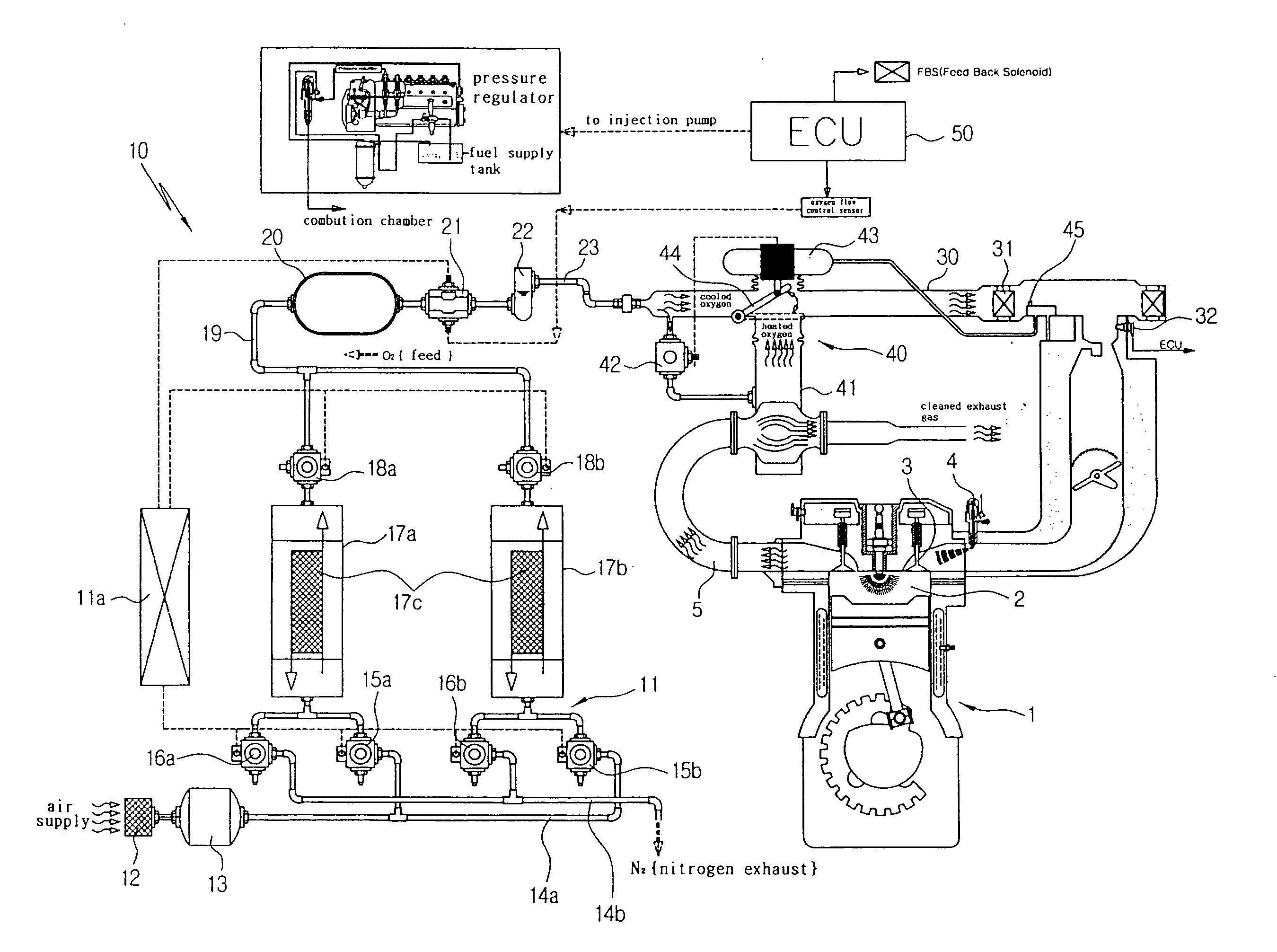
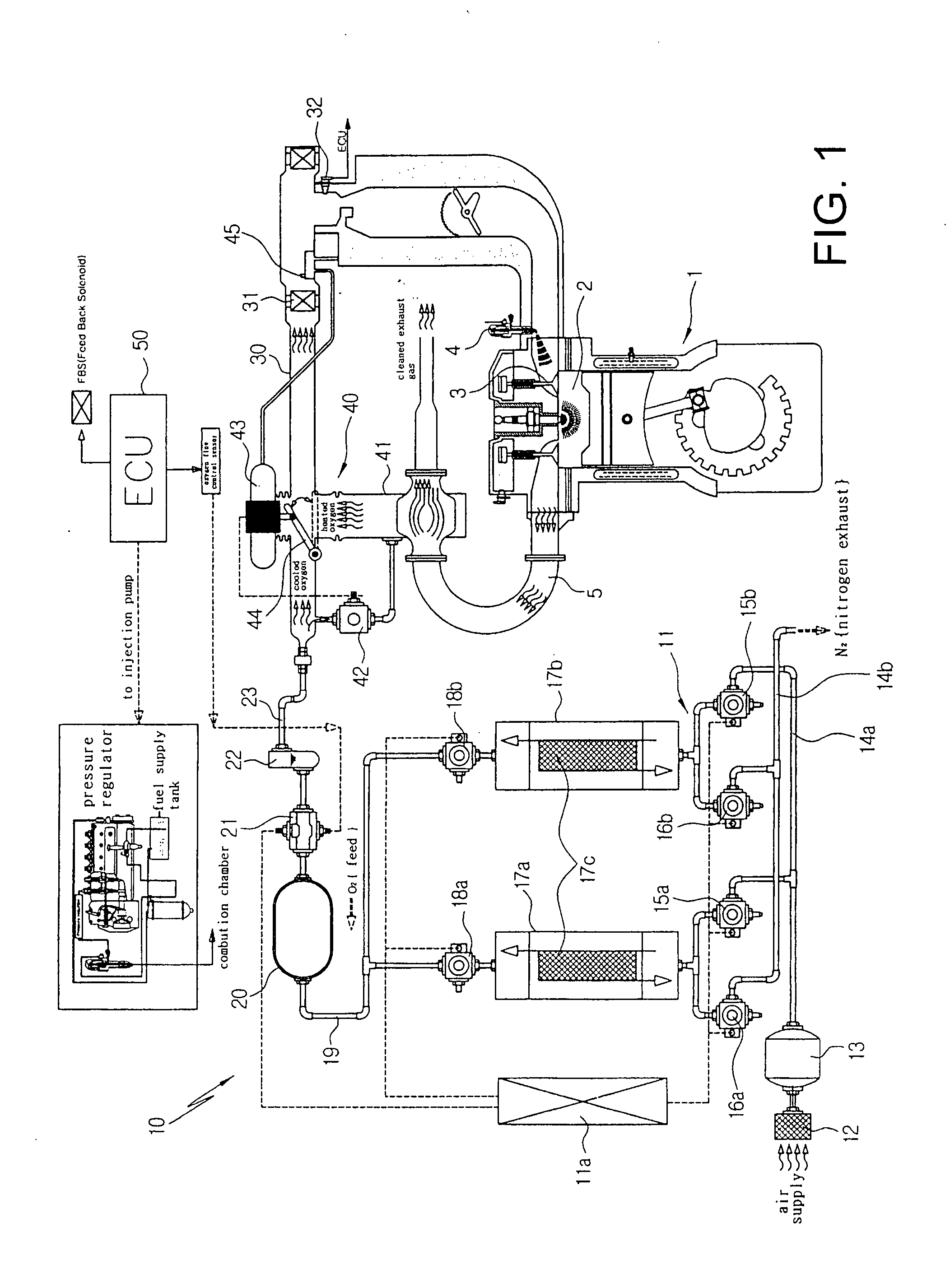
[0044]FIG. 1 is a view illustrating a diesel engine equipped with a low-fuel consumption and low-pollution combustion system for supplying a vehicle engine with a mixture of fuel and oxygen according to the present invention.

[0045] The low-fuel consumption and low-pollution combustion system 10 for supplying the vehicle engine with the mixture of fuel and oxygen is applicable for a diesel engine system 1, a gasoline engine 1 and an LPG engine 1. Since the structure and operation of each engine 1 are generally known in the art, they will not be further described below.

[0046] First, as shown in FIG. 1, according to the low-fuel consumption and low-pollution combustion system 10 applied to the diesel engine 1, intake air supplied from the exterior is absorbed in adsorption towers 17a and 17b with predetermined pressure so as to separate oxygen contained in the intake air from nitrogen. At this time, the oxygen separated from the nitrogen is stored in an oxygen storage tank 20 and the ...

second embodiment

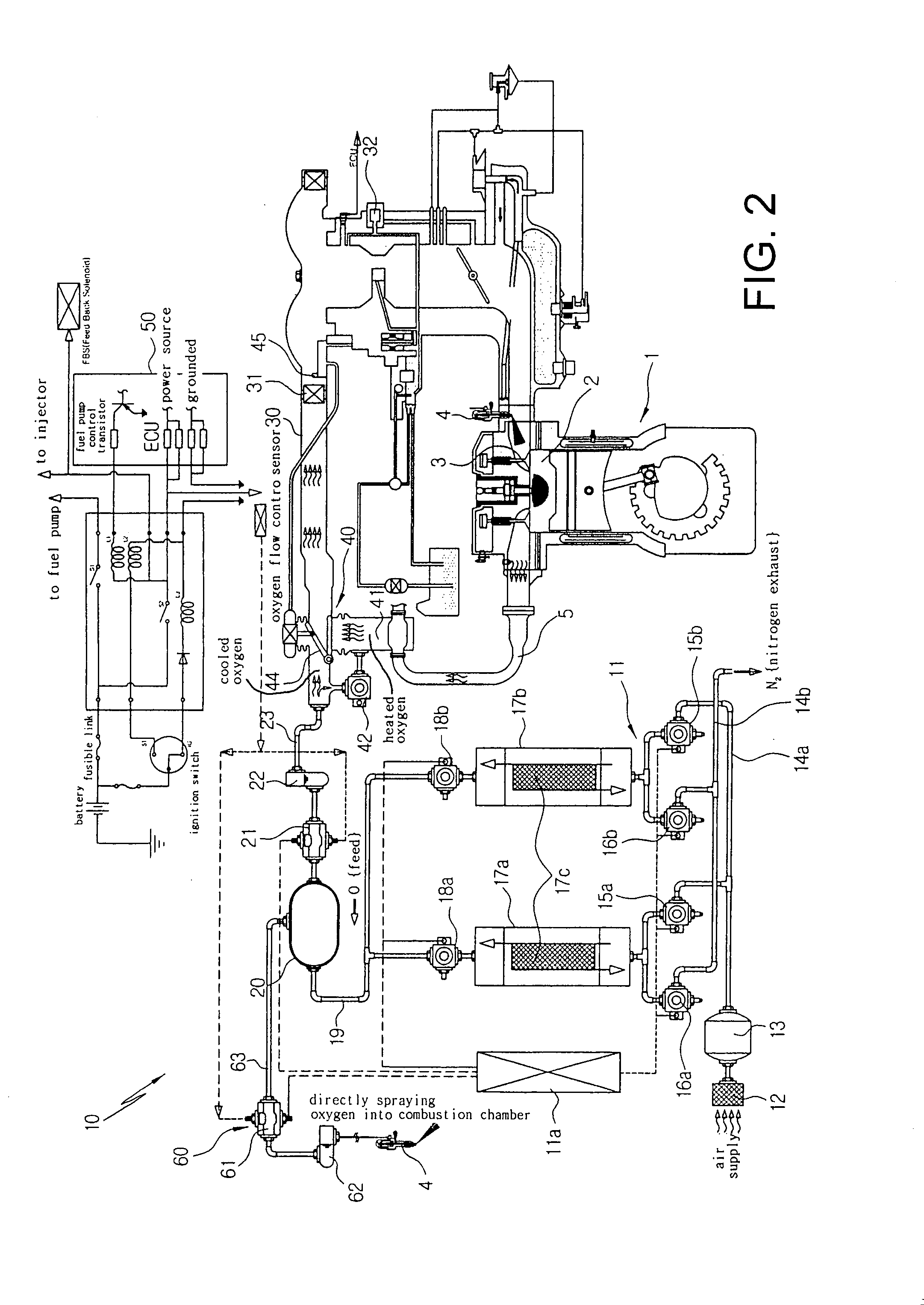
[0081] However, the low-fuel consumption and low-pollution combustion system 10 according to the present invention further includes a direct spray unit 60 for directly spraying the mixture of fuel and oxygen into the combustion chamber 2 of the engine 1.

[0082] The direct spray unit 60 includes an injector 4 installed at an upstream of an intake valve 3 of the engine 1 for simultaneously receiving, mixing and spraying oxygen and fuel, a second pressure regulator 61 connected to the transport pipe 63, which directly connects the oxygen storage tank 20 with the injector 4, in order to directly feed oxygen stored in the oxygen storage tank 20 to the injector 4 while regulating pressure of the oxygen, and a second oil / water separator 62 connected to the transport pipe 63 so as to separate water from the oxygen.

[0083] Accordingly, the second pressure regulator 61 directly feeds the oxygen stored in the oxygen storage tank 20 into the injector 4 through the transport pipe 63 and the injec...


PUM


Abstract

A low-fuel consumption and low-pollution combustion system supplies an engine with a mixture, in which oxygen contained in air is separated from nitrogen through a PSA (pressure swing adsorption) whereby oxygen having purity above 95% and a fuel mixture is fed into and burned in the combustion chamber obtaining a desired engine output with low-fuel consumption. Nitrogen is previously removed so that nitride oxide can be minimized during combustion procedure and CO and toxic gas derived from incomplete combustion can be minimized. The system obtains high engine output and low-fuel consumption by reducing toxic gas derived from incomplete combustion. The system includes an oxygen separator for separating oxygen from nitrogen by introducing external air into adsorption towers with predetermined pressure while storing the oxygen separated from the nitrogen in an oxygen storage tank and exhausting the nitrogen.

Description

TECHNICAL FIELD [0001] The present invention relates to a low-fuel consumption and low-pollution combustion system for supplying a vehicle engine with a mixture of fuel and oxygen. More particularly, the present invention relates to a low-fuel consumption and low-pollution combustion system for supplying a vehicle engine with a mixture of fuel and oxygen, in which oxygen contained in air is separated from nitrogen through a PSA (pressure swing adsorption) scheme so that oxygen having purity above 95% is obtained and a mixture of fuel and oxygen is fed into a combustion chamber of the vehicle engine and burned in the combustion chamber of the vehicle engine, thereby obtaining a desired engine output with low-fuel consumption, and in which nitrogen (N2) is previously removed so that an amount of nitride oxide (Nox) can be minimized during the combustion procedure and CO and toxic gas derived from incomplete combustion can be minimized by achieving complete combustion. BACKGROUND ART [...

Claims


Application Information

Patent Timeline
Patent Type & Authority Applications(United States)
IPC IPC(8): F02M69/04F02M25/00F02M25/10
CPCF02D41/1456Y02T10/121F02M25/10Y02T10/12F02M25/00
Inventor HA, YEONGGILKIM, YUNHA
Owner KOREA ENVIRONMENT TECH
Learn More