Translucent laminate sheet and light-emitting device using the translucent laminate sheet

a technology of translucent laminate and light-emitting device, which is applied in the direction of discharge tube luminescnet screen, lighting and heating apparatus, instruments, etc., can solve the problems of difficult to obtain white light having high chromaticness and disclose a light-emitting device, and achieve low color deterioration in organic phosphor, reduce color variation, and high color reproducibility and chromaticness

Inactive Publication Date: 2007-11-29
CITIZEN ELECTRONICS CO LTD
View PDF8 Cites 109 Cited by
  • Summary
  • Abstract
  • Description
  • Claims
  • Application Information

AI Technical Summary

Benefits of technology

[0015] Because the organic phosphor in the translucent laminate sheet according to the present invention is hermetically sealed in the light-transmitting members, there is less deterioration in the organic phosphor and the initial characteristics can be maintained over a long period.
[0016] Also, because the light-emitting device uses the translucent

Problems solved by technology

However, because the YAG phosphor is an inorganic phosphor, the wavelength-converted light has a wide spectrum and has poor matching with a liquid crystal color filter, and hence it is difficult to obtain white light having high chromaticness.
However, th

Method used


Image

  • Translucent laminate sheet and light-emitting device using the translucent laminate sheet
  • Translucent laminate sheet and light-emitting device using the translucent laminate sheet
  • Translucent laminate sheet and light-emitting device using the translucent laminate sheet

Examples


example 1

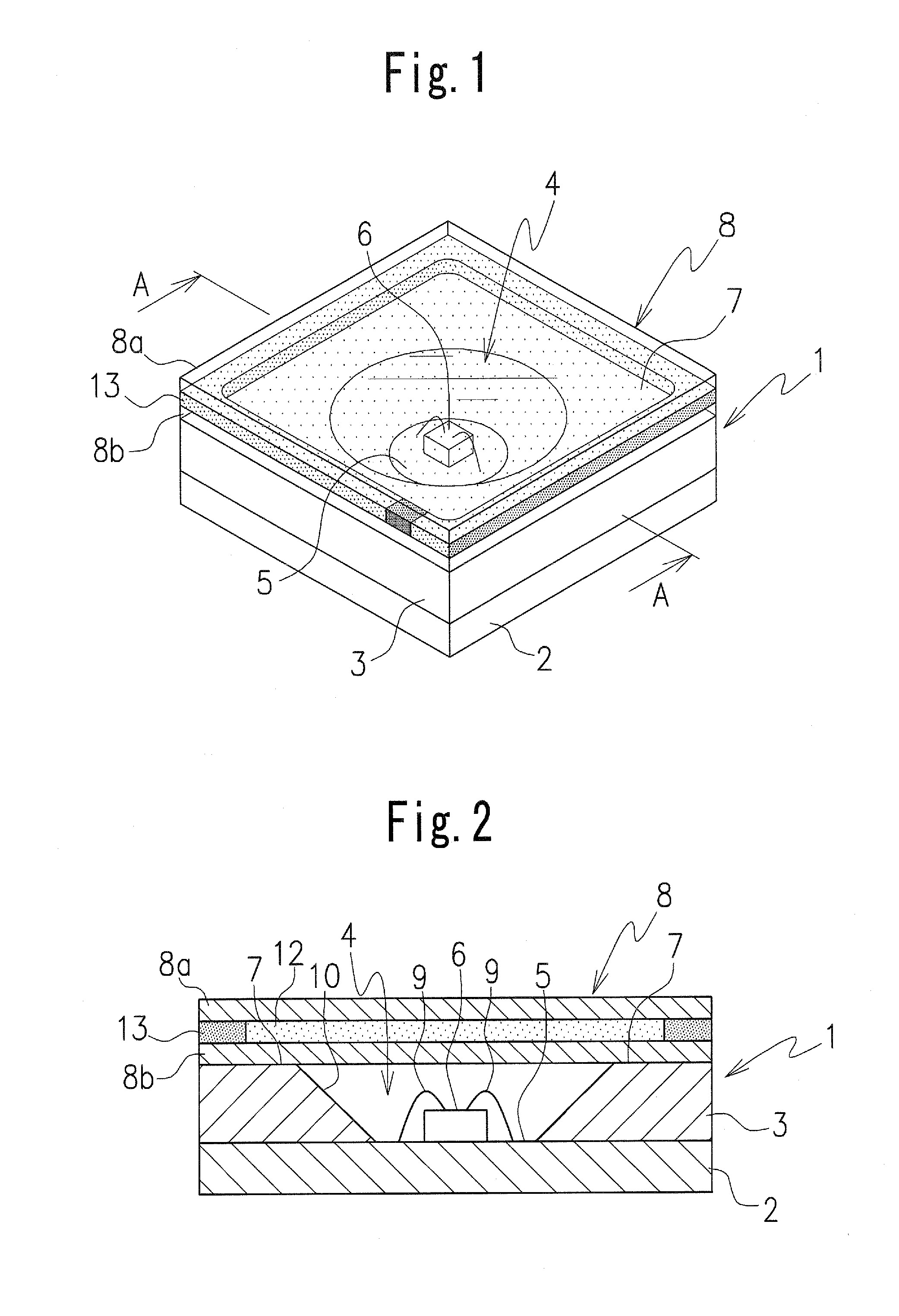
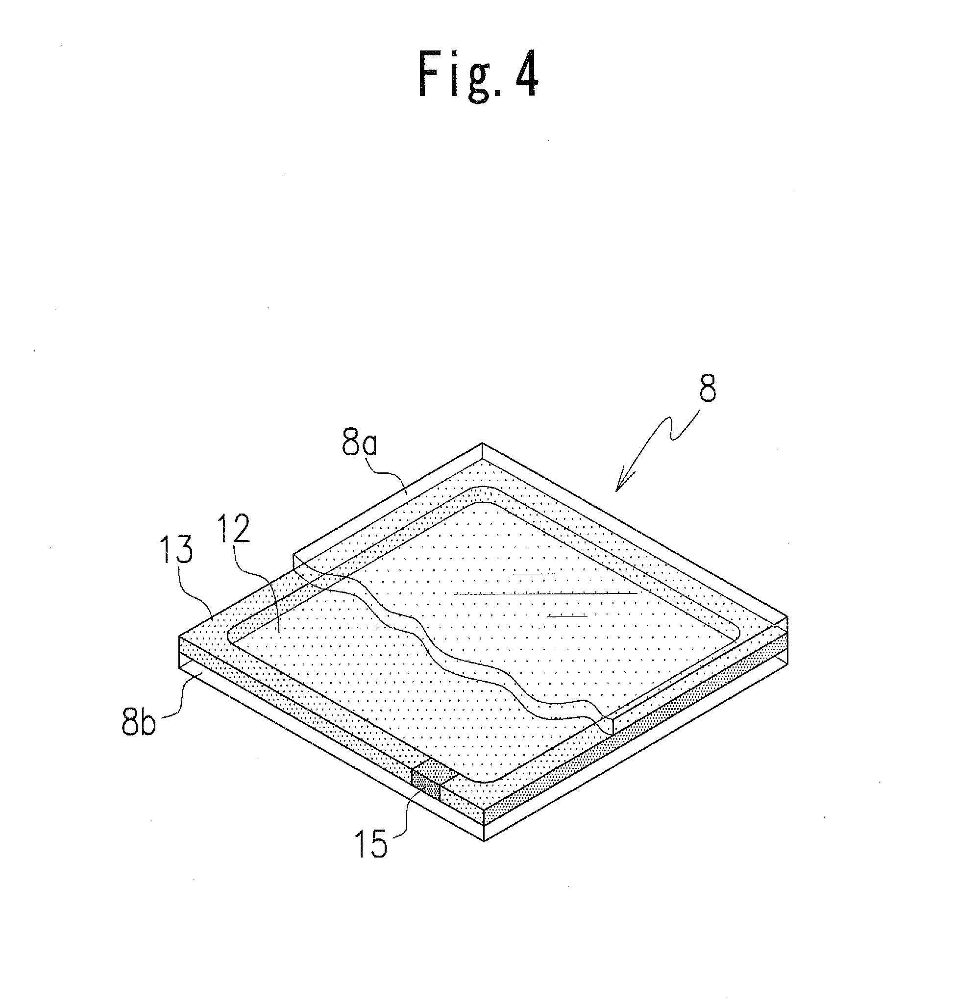
[0077] A translucent laminate sheet was disposed in front of a near-ultraviolet LED, GU35S400T ( central wavelength: 400 nm, made by Showa Denko Co., Ltd). A special thin glass plate (white glass plate), D263No.2 (heat expansion coefficient: 73×107 / ° C.) made by Spiegel Glass Company in Germany was used for each of two glass plates in the translucent laminate sheet. More specifically, glass plates each having a size of 5.0 mm×5.0 mm and a thickness of 0.21 mm were used. A paste of the aforementioned europium complex compound [a combination of X═H, Y═CF3, Z═H, p=2, q=3 in the chemical structural equation (1)] was disposed between the glass plates, and the glass plates between which the paste was disposed were fusion-bonded with an Sn-type solder, in a nitrogen atmosphere. A eutectic alloy (melting point: 139° C.) having Bi of 58% by mass, made by Senjyu Einzoku Co., Ltd, was used as the Sn-type solder.

[0078] As a result, red emission light with high color reproducibility was observe...

example 2

[0079] Two plates of glass D263 No.2 ( thickness: 0.21 mm) of the aforementioned white glass plate were prepared. The plates of glass were washed by using a water-type cleaning material and then dried by steam. The glass plate planned to be disposed at an upper side was dried at 300° C., after a fritted glass paste has been printed thereon.

[0080] A fritted glass paste was printed on the lower glass plate. The above-mentioned printing was executed by screen-printing using a 400 mesh stainless screen plate. The paste has a wet thickness of 10 μm. Part number # 4017C, made by Electro-Science Laboratory Co., Ltd., was used for the fritted glass plate.

[0081] Next, the upper glass plate and the lower glass plate were laminated to form a unit, which was baked. A gap between the glass plates when laminating the glass plates was set to be 100 μm. The baking was carried out at 100° C. for 30 minutes (with solvent drying), 350° C. for 45 minutes, and 480° C. for 1 hour, taking a total of 3 h...

example 3

[0086] In addition to the europium complex compound (red phosphor) in the first embodiment, a paste made of each of BaMgAl10O17: Eu (blue phosphor) and ZnS: Cu (green phosphor) was used. Apart from the use of an organic phosphor in which a mixture of the blue and green phosphors was dispersed in polyvinyl alcohol, the same operation as in the first embodiment was carried out to produce the translucent laminate sheet. A light-emitting device was assembled by using the translucent laminate sheet, in the same way as in the first embodiment. White emission light with high color reproducibility was observed.


PUM


Abstract

A translucent laminate sheet includes at least one type of organic phosphor to make wavelength conversion of light emitted from a light source, and light-transmitting members to seal the organic phosphor. The light-transmitting members are formed by two plate-like members and the organic phosphor is disposed to be held between the two plate-like members. A frame member is disposed between the two plate-like members, and the organic phosphor is hermetically sealed in a space surrounded by the frame member and the two plate-like members.

Description

BACKGROUND OF THE INVENTION [0001] 1. Field of the Invention [0002] The present invention relates to a translucent laminate sheet configured to emit white light by means of an organic phosphor and a light-emitting device using the translucent laminate sheet. [0003] 2. Description of Related Art [0004] A known example of a conventional light-emitting device comprises an LED (light emitting diode) lamp in which an LED element is mounted on a lead frame or insulative substrate provided with electrodes using an Ag paste and electrically connected to the electrodes by bonding wires, and is thereafter sealed by epoxy resin, silicon resin or the like. In the case of realizing a white-light LED lamp, a blue LED element of a GaN type is mainly used, and the LED lamp is formed by mixing a YAG phosphor in the above-mentioned epoxy resin or the like, so that pseudo white light is emitted by wavelength conversion of light emitted from the blue LED element by the YAG phosphor (for reference, see ...

Claims


Application Information

Patent Timeline
IPC IPC(8): H01J1/62H01J63/04
CPCC09K11/06C09K2211/1007C09K2211/1014C09K2211/182F21K9/56F21Y2101/02H01L2224/48091H01L33/505H05B33/14H01L2924/00014H01L2924/12044F21K9/64F21Y2115/10H01L2924/00
Inventor HORIUCHI, MEGUMIYUKINARI, TOSHIRO
Owner CITIZEN ELECTRONICS CO LTD
Why Eureka
Try Eureka