Multilayer film and image display device

a display device and film technology, applied in the field of multi-layer film and image display devices, can solve the problems of uneven luminance distribution, rainbow effect, and difficulty in keeping adhesive strength high, and achieve the effects of excellent optical properties, reduced color rainbow effect, and increased adhesive strength

Inactive Publication Date: 2007-11-29
FUJIFILM CORP
View PDF24 Cites 21 Cited by
  • Summary
  • Abstract
  • Description
  • Claims
  • Application Information

AI Technical Summary

Benefits of technology

[0015] According to the present invention, the adhesive strength is increased between the base and the layers, and the color rainbow effect is reduced. It is also possible to produce a variety of optical films, such as a prism film, a hard hard coat film, and an anti-reflection film, with excellent optical properties by forming a

Problems solved by technology

However, the adhesive strength is not easily kept high because it is susceptible to the differences in composition, a forming condition, and other parameters among the base and the upper layers.
In the multilayer film, however, light beams will reflect at the boundaries of the base to the adhesive layer, the adhesive layer to the upper layer, and the upper layer to the air, and such reflected light beams interfere with each other to cause uneven luminance distribution that gives a rainbow color (hereinafter, color rainbow effect).
The color rainbow effect, w

Method used


Image

  • Multilayer film and image display device
  • Multilayer film and image display device
  • Multilayer film and image display device

Examples


working example 1

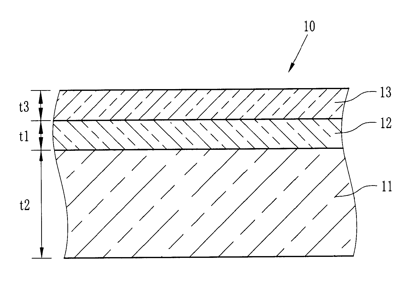
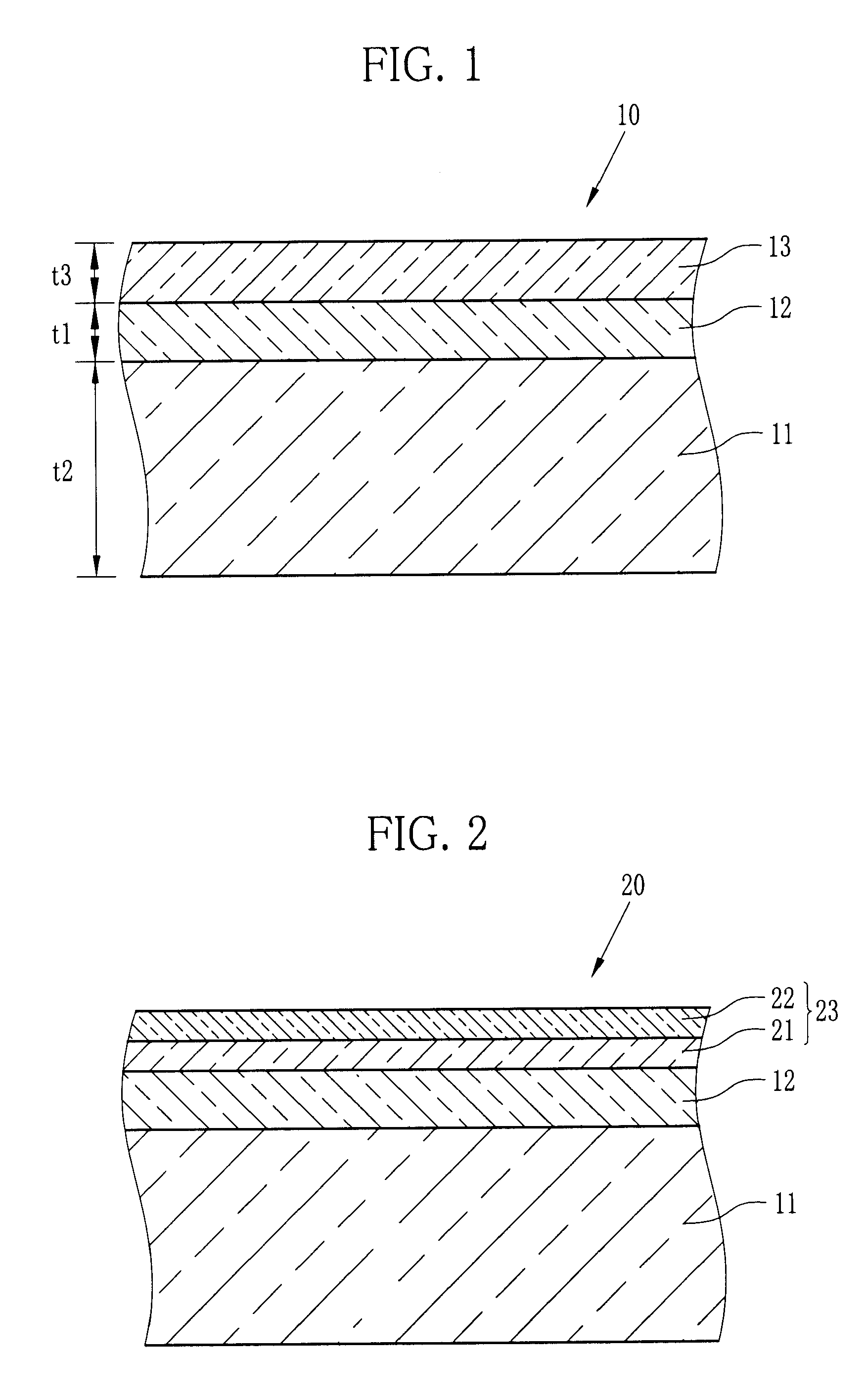
[0075] The multilayer film 10, shown in FIG. 1, was produced as a working example 1 by the following procedure. The second layer 13 was composed of only the hard coat layer 21.

[0076] (Base)

[0077] Firstly, polyethylene terephthalate (hereinafter, PET) polycondensed with antimony trioxide catalyst to have intrinsic viscosity of 0.66 was dried out to include a moisture content of 50 ppm or less, and then melted in an extruder at 280-300° C. This molten PET resin was cast from a die onto an electrostatically energized chill roll, and an amorphous film was obtained. This amorphous film was stretched, firstly along the longitudinal direction until it gets 3.3 times as large as the initial length, and then along the width direction until it gets 3.8 times as large as the initial width, so that the base 11 with a 100 μm thickness was obtained. The refractive index of this base 11 was 1.65.

[0078] (First Layer)

[0079] The base 11 was conveyed at a speed of 70 m / min, and a corona discharge ...

working example 2

[0095] A working example 2 was produced by the same manner as the working example 1, except that the 2nd particle water dispersion in the coating liquid A was changed to zirconium oxide water dispersion. This zirconium oxide water dispersion was a zirconium oxide sol (HZ-307W6: Nissan Chemical Industries, Ltd.: 20% solid content aqueous solution), and the amount was 153 pts.mass.

working example 3

[0096] A working example 3 was produced by the same manner as the working example 1, except that the 2nd particle water dispersion in the coating liquid A was changed to indium oxide water dispersion. The indium oxide water dispersion was EP ITO DL-1 (product name: JEMCO Inc.: 20% solid content aqueous solution), and the amount was 115 pts.mass.


PUM

PropertyMeasurementUnit
Thicknessaaaaaaaaaa
Thicknessaaaaaaaaaa
Lengthaaaaaaaaaa

Abstract

A multilayer film is produced by forming a first and a second layers consecutively on at least one surface of a biaxially stretched polyester base. The first layer contains particles and a binder both composed mainly of either tin oxide, indium oxide, zirconium oxide, or titanium oxide. When the refractive indexes of the base, the first layer, and the second layer are represented by η1, η2, and η3 respectively, the first layer and the second layer are adjusted for the refractive index such that the differences |η1−η2| and |η1−η3| are both not greater than 0.03. Adhesive strength is therefore kept high between the base and the layers to eliminate light interference, and the multilayer film offers an excellent optical property with few color rainbow effect.

Description

FIELD OF THE INVENTION [0001] The present invention relates to a multilayer film and image display devices equipped with this multilayer film. BACKGROUND OF THE INVENTION [0002] As image display devices of all kinds, such as liquid crystal display devices, plasma display devices, organic EL display devices, surface-conduction electron-emitter display (SED) devices, and CRT display devices are becoming more popular these days, a demand for an optical film, one of their main components, is also increasing. The optical film is a film with various optical functions, and used for improvement of viewing angle, optical unevenness, and other optical properties to achieve a good visual quality of the image display devices. Generally, the optical film takes a multilayer structure composed of a polymer-made base and one or more upper layers. [0003] In most cases, a polyester film is used as the base because of its transparency, dimensional stability, chemical resistance, and low hygroscopicity...

Claims


Application Information

Patent Timeline
IPC IPC(8): B32B27/40B32B27/36B32B27/20C08J7/043C08J7/044C08J7/046
CPCC08J7/04C08J2367/02G02B5/208Y10T428/2495Y10S428/91Y10T428/26Y10T428/265Y10T428/256Y10T428/24942Y10T428/25Y10T428/31797Y10T428/31786Y10T428/31551C08J7/043C08J7/046C08J7/044
Inventor KOBAYASHI, TAKASHIHATAKEYAMA, AKIRANOMURA, TATSUYASUZUKI, KATSUYOSHIFUKAZAWA, HIDEO
Owner FUJIFILM CORP
Why Eureka
Try Eureka