Raman instrumentation

a raman and instrumentation technology, applied in the field of instruments, can solve the problems of substantially blind and insensitive detection of ultraviolet light by the detector, and achieve the effects of low power consumption, rugged design, and convenient handling

Inactive Publication Date: 2007-12-06
INTEVAC
View PDF25 Cites 28 Cited by
  • Summary
  • Abstract
  • Description
  • Claims
  • Application Information

AI Technical Summary

Benefits of technology

[0020]There is described, a compact novel Raman instrument. It is discussed as shaped like a small gun. The instrument has low power consumption. It is convenient to handle and store, making it ideal for field chemical substance identification. The Raman gun disclosed, because of its rugged design and high performance capabilities, offers a real tool for such field applications. Additionally, although the gun fits this particular niche well, it is not limited to such an application but may also be used for any application where Raman readings are desired.

Problems solved by technology

This results in a detector that is substantially blind to and insensitive to UV and / or visible light.

Method used


Image

  • Raman instrumentation
  • Raman instrumentation
  • Raman instrumentation

Examples


Embodiment Construction

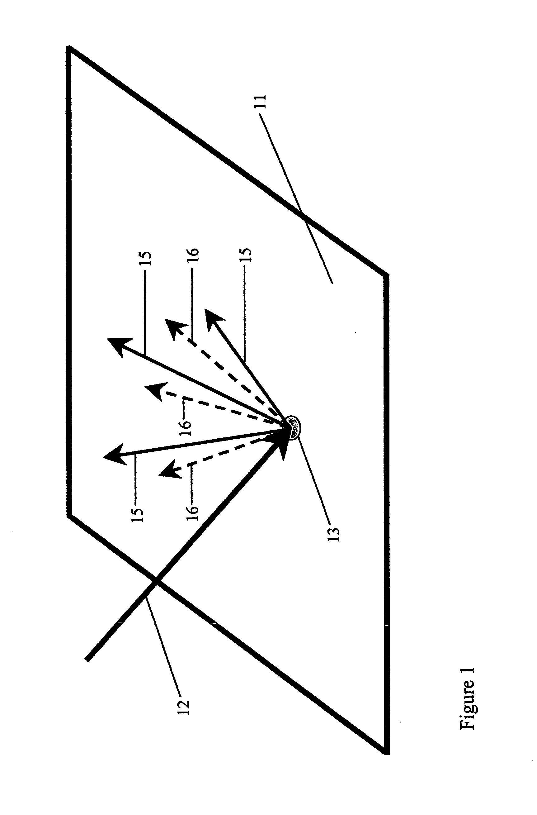
[0035]Referring now to FIG. 1, there is shown a sample 11 and an incoming incident light beam 12 that is directed to spot 13 on sample 11. Irradiating outward from spot 13 are rays of light 15 and 16. The rays 15 are indicated as continuous lines, and represent in this Figure, scattered light of the same wavelength as the wavelength of the incident light beam 12. This is referred to as Raleigh Scatter. The rays 16, indicated as dashed lines, represent scatter at a different wavelength than the incoming wavelength of the incident light beam 12. The light scattered at different wavelengths 16 is referred to as Raman scatter.

[0036]This figure illustrates the Raman effect in its simplest form. It is employed in all Raman instrumentation. It is also a basis to explain principles incorporated into the instrument of this invention. The sample 11 may comprise a material of any chemical substance. The incoming light beam is reflected back in beams that appear at the same wavelength as the in...


PUM

PropertyMeasurementUnit
wavelength rangeaaaaaaaaaa
wavelengthsaaaaaaaaaa

Abstract

A portable Raman spectroscopy instrument capable of discriminating between chemicals in the solid, liquid and vapor states is described. The instrument is in the shape of a gun and uses a solid state detector and an NIR laser. It relies on gating techniques to minimize weight and lower energy needs.

Description

FIELD OF THE INVENTION[0001]This invention relates to the field of instrumentation and more particularly to industrial and portable Raman spectrometers and spectroscopy. Raman instruments can be used to analyze chemicals in the solid, liquid, or vapor phases.BACKGROUND OF INVENTION[0002]Raman spectroscopy is a spectroscopic technique used in branches of physics and chemistry to study vibrational, rotational, and other low-frequency modes in a system. It relies on inelastic scattering, or Raman scattering of monochromatic light, usually from a laser in the visible, near infrared, or near ultraviolet range. Photons or other excitations in the system are absorbed or emitted by the laser light, resulting in the energy of the laser photons being shifted up or down. Infrared spectroscopy yields similar, but complementary information.[0003]Typically, a sample is illuminated with a laser beam (see FIG. 2). Light from the illuminated spot is collected with a lens and sent through a monochrom...

Claims


Application Information

Patent Timeline
Patent Type & Authority Applications(United States)
IPC IPC(8): G01J3/44G01N21/65
CPCG01J1/42G01J3/02G01N2021/656G01J3/44G01N21/65G01J3/0272
Inventor TACK, LESLIE M.TRUE, BRUCE
Owner INTEVAC
Why Eureka
Try Eureka