Process for Plasma Coating

a plasma coating and plasma technology, applied in the field of plasma coating, can solve the problems of limited shelf life of beverages, insufficient siosub>x /sub>forming an effective barrier to gas transmission in plastic containers, and impractical commercial purposes, and achieves the effect of increasing the barrier property and effective barrier against gas transmission

Inactive Publication Date: 2007-12-06
WEIKART CHRISTOPHERM +1
View PDF6 Cites 39 Cited by
  • Summary
  • Abstract
  • Description
  • Claims
  • Application Information

AI Technical Summary

Benefits of technology

[0008] The instant invention is a solution, at least in part, to the above stated problem of plasma coating polyolefin or polylactic acid containers. The instant invention is a method for plasma coating the inside surface of a polyolefin or polylactic acid container to provide an effective barrier again

Problems solved by technology

Unfortunately, the shelf-life of the beverage is limited in plastics due to relatively high oxygen and carbon dioxide permeability.
In general, SiOx coatings provide an effective barrier to gas transmission; nevertheless, SiOx is insufficient to form an effective barrier to gas transmission for plastic containers.
Although Namild discloses the combination of the plasma polymerized silicic compound and the SiOx layer (where x is 1.5 to 2.2)

Method used


Image

  • Process for Plasma Coating
  • Process for Plasma Coating

Examples


example 1

Preparation of a Polyorganosiloxane / Silicon Oxide Coating On a Polypropylene Bottle

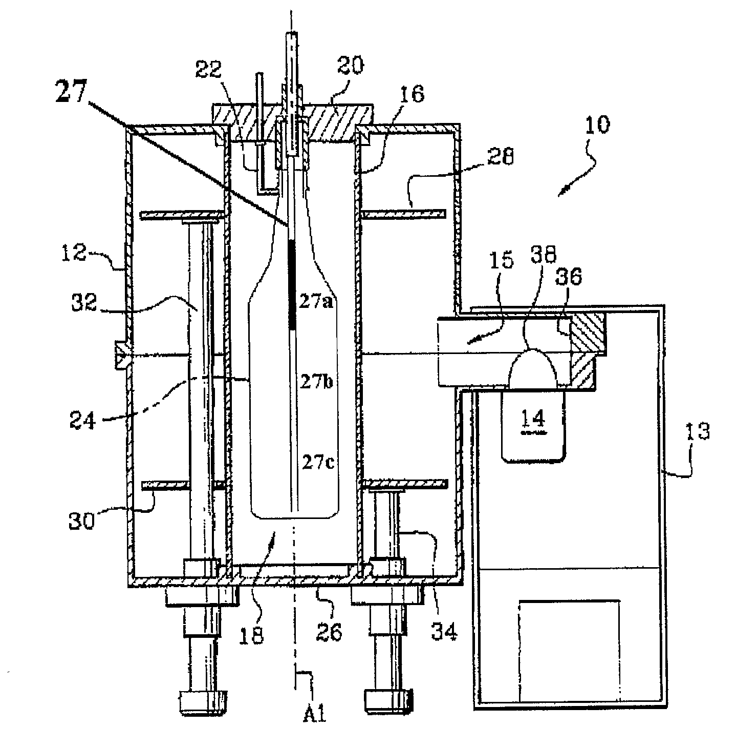
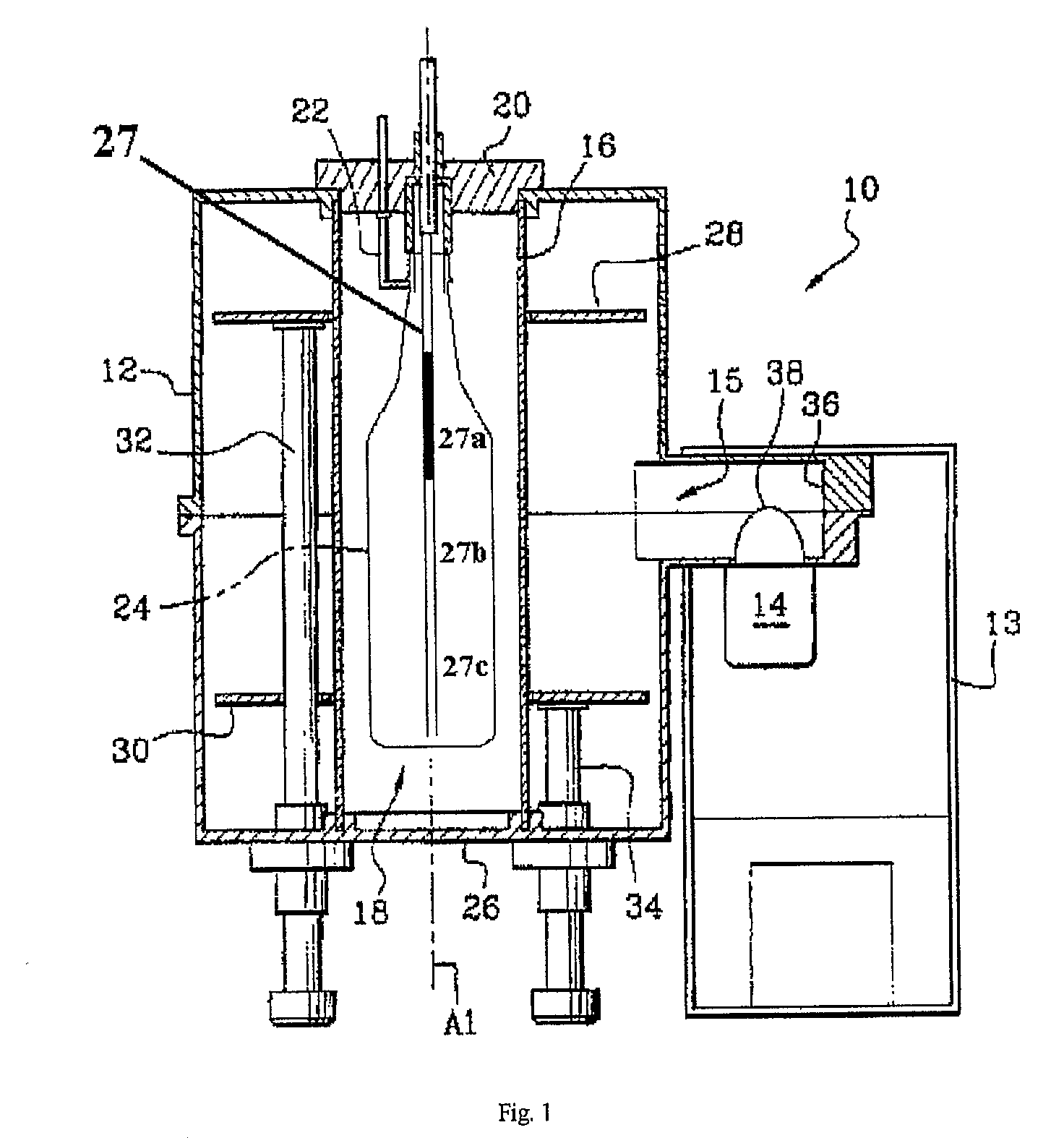
[0033] An apparatus illustrated in FIG. 1 is used for this example. In this example, container 24 is a 500 mL polypropylene bottle suitable for carbonated beverages. Bottle 24 is inserted into tube 16, which is located in resonant cavity 12. Cover 12 is adapted with an open-ended graded porous injector 27 that is fitted into bottle 24 so that injector 27 extends to about 1 cm from the bottom of bottle 24. Injector 27 is fabricated by welding together three sections of 2.5″ long (6.3 cm) porous hollow stainless steel tubing (0.25″ outer diameter (0.64 cm), 0.16″ inner diameter (0.41 cm)), each tubing with a different porosity, to form a single 7.5″ (19 cm) graded injector as illustrated in FIG. 1. The top third of injector 27a has a pore size of about 20 μm, the middle third of the injector 27b has a pore size of about 30 μm, and the bottom third of the injector 27c has a pore size of about 50 μm. (P...

example 2

Preparation of an Amorphous Carbon Coating on a Polypropylene Bottle

[0041] A partial vacuum is established on both the inside and the outside of bottle 24. The outside of bottle 24 is maintained at 80 mbar and the inside is maintained initially at about 10 μbars. A gas consisting essentially of acetylene is flowed through injector 27 at a flow rate of 160 sccm, at a pressure of 160 μbars, using a power of 300 watts for a time of 3 seconds. Then nitrogen is flowed through injector 27 at a flow rate in the range of 10 scam, at a pressure of 160 μbars, using a power of 100 watts for a time of ten seconds.

[0042] The amorphous carbon layer is adherent and has a thickness of about 150 nm. Barrier performance is indicated by a barrier improvement factor (BIF), which denotes the ratio of the oxygen transmission rate of the uncoated injection stretch blow molded polypropylene bottle to the coated bottle. The BIF is measured using an Oxtran 2 / 20 oxygen transmission device (available from M...


PUM

PropertyMeasurementUnit
Poweraaaaaaaaaa

Abstract

The present invention describes a method for plasma coating the inside surface of a polyolefin or a polylactic acid container to provide an effective barrier against gas transmission. The method provides a way to deposit rapidly and uniformly very thin, adherent and nearly defect-free layers of polyorganosiloxane and silicon oxide (or amorphous carbon) on the inner surface of the container to achieve more than an order of magnitude increase in barrier properties.

Description

CROSS REFERENCE STATEMENT [0001] This application claims the benefit of U.S. Provisional Application Nos. 60 / 618,497 and 60 / 627,593 filed Oct. 13, 2004 and Nov. 12, 2004, respectively.BACKGROUND [0002] The present invention relates to a process for depositing a plasma-generated coating onto a container, more particularly onto the inside surface of a polyolefin or polylactic acid container. [0003] Plastic containers have been used to package carbonated and non-carbonated beverages for many years. Plastics such as polyethylene terephthalate (PET) and polypropylene (PP) are preferred by consumers because they resist breakage, and they are light-weight and transparent. Unfortunately, the shelf-life of the beverage is limited in plastics due to relatively high oxygen and carbon dioxide permeability. [0004] Efforts to treat plastic containers so as to impart low oxygen and carbon dioxide permeability are known. For example, Laurent et al. (WO 9917333) describes using plasma enhanced chemi...

Claims


Application Information

Patent Timeline
IPC IPC(8): C08J7/04C23C16/04
CPCC08J7/123C08J2323/12C08J2367/04H01J37/32192C23C16/045C23C16/511C23C16/0245
Inventor WEIKART, CHRISTOPHERMSMITH, TODD D.
Owner WEIKART CHRISTOPHERM
Why Eureka
Try Eureka