Microfabricated Compositions and Processes for Engineering Tissues Containing Multiple Cell Types

a technology of multiple cell types and compositions, applied in the field of three-dimensional tissue engineered systems, can solve the problems of integrating these devices and tissues within the host, engendering processes, inflammation and clotting, etc., and achieves the effect of reducing the total volume of polymer and reducing the complexity of device fabrication

Active Publication Date: 2007-12-06
CHARLES STARK DRAPER LABORATORY +1
View PDF28 Cites 91 Cited by
  • Summary
  • Abstract
  • Description
  • Claims
  • Application Information

AI Technical Summary

Benefits of technology

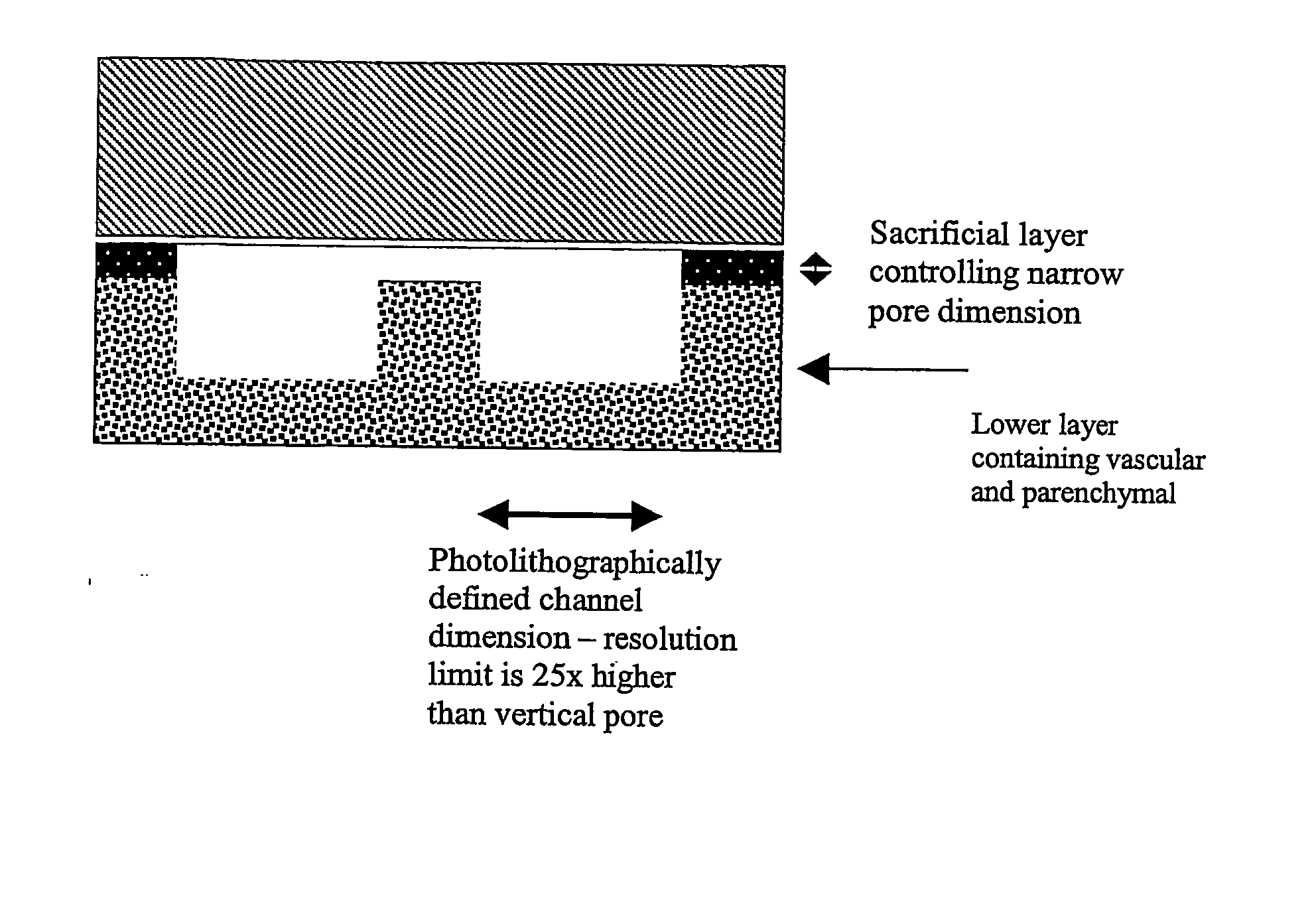
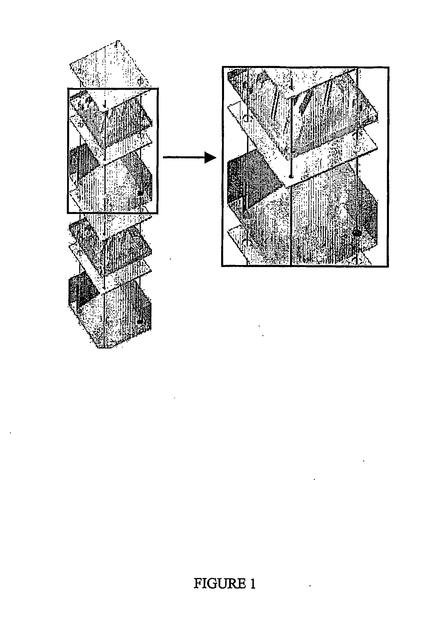
[0013] The present invention differs from former approaches, which require three separate layers, one for the vascular network, one for the membrane, and one for the organ-specific (e.g., parenchymal cells), in order to build a single “unit cell” for stacking. The present invention incorporates each of these three layer functions into a single layer, integrated with adjacent layers, greatly reducing the complexity of the device fabrication. Former methods also require that vascular and parenchymal cells be arranged on separate polymer films, separated by a semipermeable membrane in the z-axis. Systems of the present invention divide the vascular and parenchymal cells with micropores or nanopores connecting the cell compartments within the same layer. As a result, the total volume of polymer is reduced by as much as a factor of three, since roughly the same number of total cells are contained within one polymer film rather than the three layers making up each organ subunit.

Problems solved by technology

The principal disadvantages of mechanical devices and xenotransplantation involve the challenges of integrating these devices and tissues within the host.
In the former case, mechanical devices utilize materials that are foreign to the host and therefore engender processes such as inflammation and clotting.
Additionally, mechanical devices are inherently temporary in nature, since they require artificial power supplies, control circuitry and other features that can never fully integrate into a natural system.
In the case of xenotransplantation, the human immune system is designed to reject cells and tissues from foreign species and therefore, immune system suppression and its inherent risks remain a challenge.
Additional risks involve the transmission of genetic viruses from the donor animal to the host.
All of these methods lack the resolution necessary to fashion the finest features of the organ, such as the capillaries, which predominate the circulatory supply.
One of the principal drawbacks of the foregoing approach involves the restrictions on the design of organ structures.
For instance, the stacking approach described above results in capillary beds that are oriented laterally within the polymer film containing the vascular network, but does not allow for vertically oriented blood vessels other than the inflow and outflow pipes integrating the entire network.
This restriction results in a limited density of capillaries within the three-dimensional structure; the ratio of small blood vessels to large vessels is not nearly as high as it is in physiological systems.

Method used


Image

  • Microfabricated Compositions and Processes for Engineering Tissues Containing Multiple Cell Types
  • Microfabricated Compositions and Processes for Engineering Tissues Containing Multiple Cell Types
  • Microfabricated Compositions and Processes for Engineering Tissues Containing Multiple Cell Types

Examples


example 1

Fabrication of Silicon and Poly(Dimethylsiloxane) Molds

[0126] Photolithography is the first step in micromachining silicon to define the nanoscale features that comprise the base layer. In this first step, a photosensitive surface (photoresist) was etched through the use of light. The photoresist was selectively exposed using a designed template and then the exposed areas were chemically removed in a developer. For this process, approximately 10 ml of Shipley's 1822 photoresist was used. The photoresist was spun onto the silicon wafer at 5000 rpm, resulting in a resin thickness of approximately 2 μm. The areas to be etched away were exposed in a Karl-Suss mask aligner. After exposure and development, the portions of the silicon that were to be etched into the vascular bed were visible and the parts that were not etched were protected by the photoresist.

[0127] The prepared wafer was subsequently used to perform a deep reactive ion etch using a Surface Technology Systems (STS) ion e...

example 2

Compression Molding of PLGA

[0130] The cross-linked PDMS mold was used to press melted poly(lactide co-glycolide) (PLGA) into the desired layer structure. A PDMS mold with a test pattern called J-Pore was placed on a rigid metal plate and roughly 6 grams of Medisorb low IV PLGA 85:15 polymer pellets were spread across the entire surface of the mold (FIG. 15, 16). A top PDMS mold with an unpatterned surface was placed over the pellet-covered bottom mold, while another rigid metal plate was placed on top of the stack. The entire stack was then placed on a hotplate at a temperature exceeding the glass transition temperature (>55° C.). During heating, approximately 100-300 lbs of force was applied to the stack for 8 minutes. After 8 minutes of simultaneous heat and pressure, the stack was removed and the two rigid metal plates were removed. The PDMS stack was placed on a flat metal surface and a large metal weight was placed on top of the stack to press it during the cooling step. The s...

example 3

Connecting and Bonding the Device

[0131] The PLGA layer was placed design-side down on a piece of PDMS. A 16-gauge syringe needle was heated with a heat gun and poked through the inlets and outlets of the PLGA layer generating four through-holes in each layer. The PLGA layer was then placed on a piece of cardboard with holes punched out beneath the through-holes. About 2 inches of size 020 silastic tubing was poked through each through-hole such that about 1 centimeter protruded on the design side. The tubes were secured in place by applying a small amount of urethane around the circumference of the tube. Urethane was allowed at least 30 minutes to dry. Any urethane and tubing on the design side of the PLGA layer was trimmed off with a sharp square razor blade.

[0132] When brought into molecular contact at a temperature above their glass transition temperature, the macroscopic interface between the surfaces of two pieces of similar polymer gradually disappeared and the interface's m...


PUM

PropertyMeasurementUnit
diameteraaaaaaaaaa
diameteraaaaaaaaaa
temperaturesaaaaaaaaaa

Abstract

The present invention relates to a three-dimensional system, and compositions obtained therefrom, wherein individual layers of the system comprise channels divided longitudinally into two compartments by a centrally positioned membrane, and wherein each compartment can comprise a different cell type.

Description

CROSS-REFERENCE TO RELATED APPLICATIONS [0001] This application claims priority from U.S. Provisional Application Ser. No. 60 / 472,230, filed on May 21, 2003. Reference is made here in to International Application No. PCT / US04 / 01098, filed Jan. 16, 2004. Reference is also made herein to U.S. Ser. No. 10 / 187,247, filed Jun. 28, 2002, which claims priority to U.S. Ser. No. 60 / 367,675, filed Mar. 25, 2002, and which is a CIP of Ser. No. 09 / 560,480, filed Apr. 28, 2000, now U.S. Pat. No. 6,455,311, which claims priority to U.S. Ser. No. 60 / 165,329, filed Nov. 12, 1999 and to U.S. Ser. No. 60 / 131,930, filed Apr. 30, 1999, the contents each of which are expressly incorporated herein by reference. Reference is also made herein to International Appln. No. PCT / US03 / 29880, which claims priority to U.S. Ser. No. 60 / 412,981, filed on Sep. 23, 2002, and U.S. Ser. No. 60 / 449,291, filed on Feb. 21, 2003, the contents each of which are expressly incorporated herein by reference. [0002] Each of the a...

Claims


Application Information

Patent Timeline
Patent Type & Authority Applications(United States)
IPC IPC(8): C12N5/06C12M1/00A01NA61F2/00C12N5/00C12N5/071C12N11/04C12N11/08C12N11/14
CPCC12N5/0062C12N2533/40C12N5/0697C12N5/0068B33Y80/00
Inventor VACANTI, JOSEPH P.BORENSTEIN, JEFFREY T.WEINBERG, ELI
Owner CHARLES STARK DRAPER LABORATORY
Why Eureka
Try Eureka