Pumped refrigerant loop cooling system for cooling High thermal density heat loads

a technology of heat load and cooling system, which is applied in the field of cooling of electrical and electronic components, can solve the problems of increasing thermal density, reducing the life of equipment, and unreliable performance, and achieves the effect of high thermal density

Inactive Publication Date: 2007-12-13
MARSALA JOSEPH
View PDF2 Cites 20 Cited by
  • Summary
  • Abstract
  • Description
  • Claims
  • Application Information

AI Technical Summary

Benefits of technology

[0011]Accordingly, it is an object of the present invention to provide cooling to electrical and electronic components. It is a further object of the present invention to provide such cooling using a pumped refrigerant loop to cool high thermal density computer and telecommunication racks and enclosures.

Problems solved by technology

Advancements in information technology (IT) equipment present challenges in creating a more effective IT environment in data centers and networking facilities.
Insufficient cooling air can cause overtemperature shutdown and unreliable performance and reduced lifetime of the equipment.
Computer and telecommunication racks and enclosures have become increasingly thermally dense.
Airflow has increased to the point where air velocity and acoustic noise are nearing unacceptable levels.
Such substantial air movement in and around racks and enclosures causes cool air to mix with heated air, thus reducing the ability of the air stream to provide cooling.
Another disadvantage of the current method is the power consumption of the fans and blowers.
As fans and blowers increase in capacity, the motors that drive them consume more power.
This, in turn, causes more heat in the enclosure and surrounding room, thus exacerbating the problem.
Dispersing all of the excess heat from the equipment and the surrounding room becomes even more of a challenge.
Yet another disadvantage of the current method of cooling enclosures occurs when air flows through the enclosure from bottom to top.
As the air heats up as it removes heat from the components within the enclosure, the air temperature can be so hot as to damage the sensitive electronic components located at or near the top of the rack or enclosure.
Still another disadvantage occurs when the cooling air moves from the front to the rear of the rack or enclosure.
This, in turn, makes it more difficult to cool this mixed air stream with the computer room air conditioner since it requires a colder evaporator than might be required if the air stream did not mix.

Method used


Image

  • Pumped refrigerant loop cooling system for cooling High thermal density heat loads
  • Pumped refrigerant loop cooling system for cooling High thermal density heat loads

Examples


Embodiment Construction

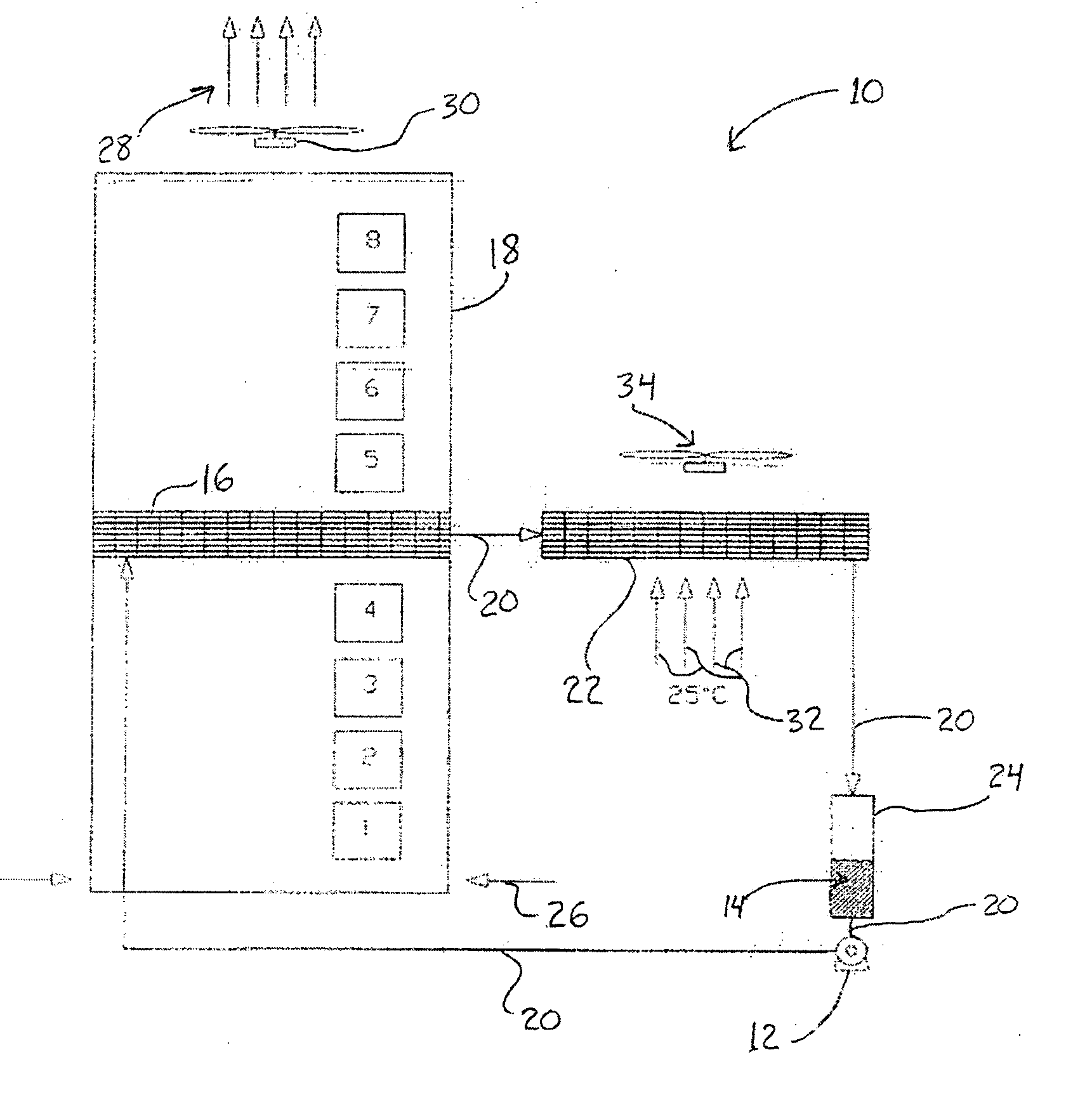
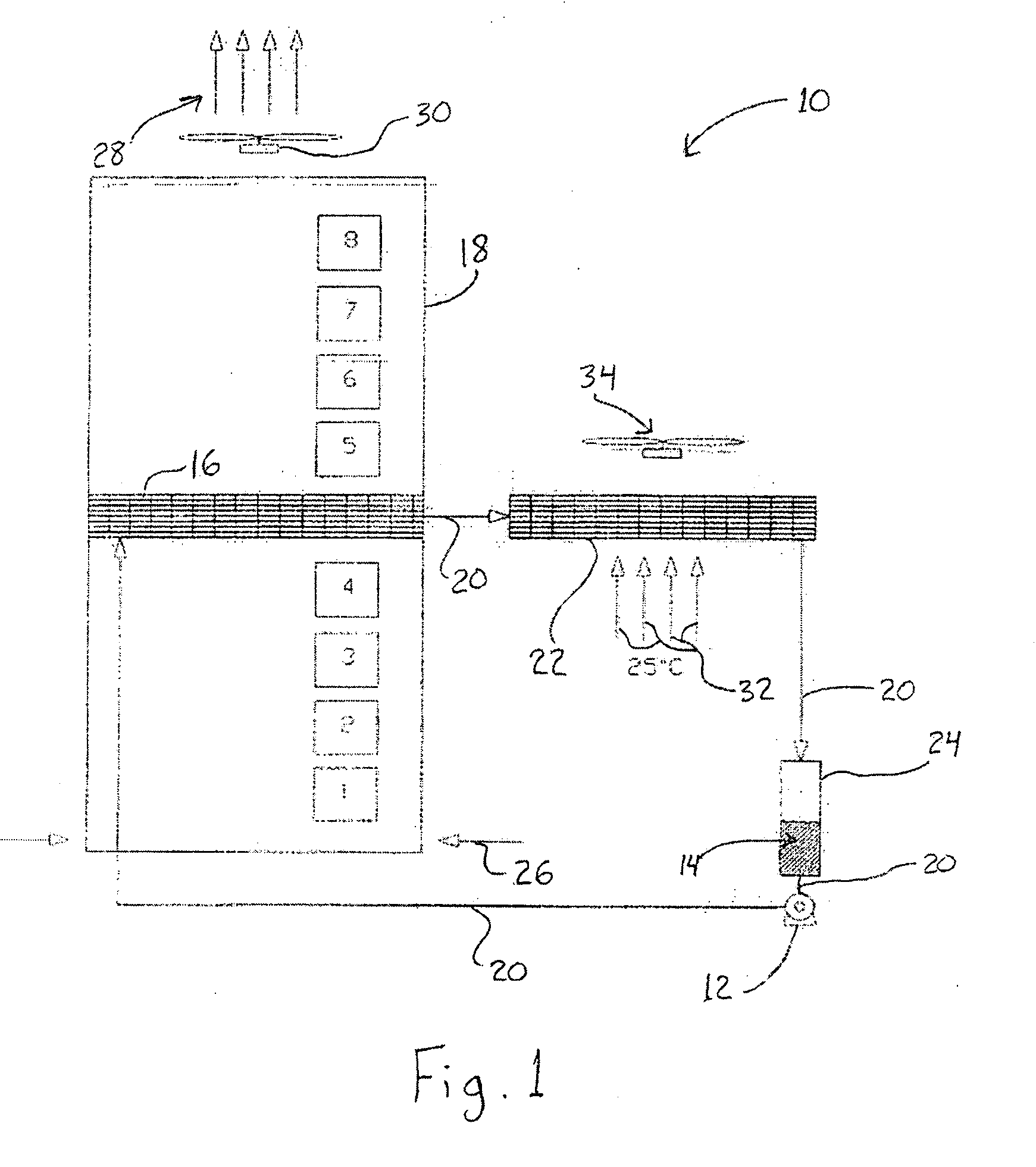
[0015]Referring to the Figure, the disclosed cooling system, illustrated as a pumped refrigerant loop system 10, includes a refrigerant pump 12 which pumps a vaporizable refrigerant 14. The vaporizable refrigerant may be any fluid which changes from a liquid to a vapor with the addition of heat and has other thermophysical properties suitable for the application. One such refrigerant is R-134a, well known to those skilled in the art. There are many other refrigerants suitable for this application which those skilled in the art could suggest as well.

[0016]Continuing with FIG. 1, the present invention uses the pump 12 to circulate the vaporizable, or volatile, refrigerant 14, as a liquid, to an evaporator device 16 located in close proximity to or in direct contact with the air stream within a computer or telecommunication rack or enclosure 18. Conduits 20 serve to transport refrigerant to the evaporator device 16, a condenser 22, a liquid receiver 24, and back to the pump 12.

[0017]Th...


PUM


Abstract

A cooling system for transferring heat from a heat load to an environment has a volatile working fluid. The cooling system includes first and second cooling cycles that are thermally connected to the first cooling cycle. The first cooling cycle is not a vapor compression cycle and includes a pump, an air-to-fluid heat exchanger, and a fluid-to-fluid heat exchanger. The second cooling cycle can include a chilled water system, or a vapor compression system, for transferring heat from the fluid-to-fluid heat exchanger to the environment. The pump circulates the vaporizable refrigerant to the evaporator device associated with the air stream within the rack or enclosure. The heated air causes the refrigerant to evaporate within the evaporator device. This evaporated refrigerant travels to a condenser device cooled by another thermally cooler fluid, causing the refrigerant to condense back to a liquid, return to the pump, and begin the cycle again.

Description

TECHNICAL FIELD[0001]The present invention relates to the cooling of electrical and electronic components, and more particularly, to use of a pumped refrigerant loop to cool high thermal density computer and telecommunications racks and enclosures.BACKGROUND OF THE INVENTION[0002]Advancements in information technology (IT) equipment present challenges in creating a more effective IT environment in data centers and networking facilities. Equipment enclosures designed for high power density applications employing servers and networking equipment typically must provide not only effective cable management and power distribution, but also adequate cooling and ventilation to assure proper and reliable operation of equipment. Insufficient cooling air can cause overtemperature shutdown and unreliable performance and reduced lifetime of the equipment.[0003]Computer and telecommunication racks and enclosures have become increasingly thermally dense. The number of electronic heat generating so...

Claims


Application Information

Patent Timeline
Patent Type & Authority Applications(United States)
IPC IPC(8): F25D17/02F25B39/04
CPCF28D15/0266H05K7/20781G06F2200/201G06F1/20
Inventor MARSALA, JOSEPH
Owner MARSALA JOSEPH
Why Eureka
Try Eureka