Device using photothermal solar energy

A technology of solar collectors and solar energy, applied in the direction of solar thermal devices, solar thermal energy, solar thermal power generation, etc., can solve problems such as single function, inconvenient management and maintenance, and increased costs

Inactive Publication Date: 2013-08-21
白坤生
View PDF6 Cites 1 Cited by
  • Summary
  • Abstract
  • Description
  • Claims
  • Application Information

AI Technical Summary

Problems solved by technology

[0002] The water level of solar heat storage water heaters is generally higher than that of collectors, which requires water supply from water towers, which is not easy to manage and maintain; although there are improvements, the cost has been greatly increased
Dish reflector solar cooker can boil water and cook, but the operating environment is not good, and the function is single
Due to the low energy density of solar energy, solar collectors heat up a large amount of working fluid slowly, especially under transient solar irradiation conditions; this is not conducive to improving the thermal energy density of working fluid and the storage and utilization of thermal energy
In fine weather, the heat energy collected by solar collectors during the day cannot be fully utilized in most cases, especially in household applications

Method used


Image

  • Device using photothermal solar energy
  • Device using photothermal solar energy
  • Device using photothermal solar energy

Examples


specific Embodiment approach 1

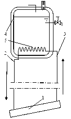
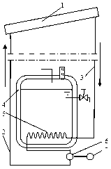
[0062] exist figure 1 with figure 2 In the shown embodiment, the outlet end of the solar heat collector 1 is airtightly connected with the inlet end of the vaporized chemical substance delivery pipe 3 that is kept warm, and the inlet end of the solar heat collector 1 is connected airtightly with the outlet end of the liquefied chemical substance delivery pipe 2. The outlet end of the vaporized chemical substance delivery pipe 3 is airtightly connected with the heat exchange pipe 5 inlet end of the heat preservation water tank 4, and the heat exchange pipe 5 outlet end of the heat preservation water tank 4 is airtightly connected with the inlet end of the liquefied chemical substance delivery pipe 2; the solar collector 1. The heat-retaining gasification medium delivery pipe 3, the heat exchange pipe 5 of the heat preservation water tank 4, and the liquefied chemical medium delivery pipe 2 are connected into a closed loop; The inlet end of the exchange pipe 5 is higher than t...

specific Embodiment approach 2

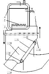
[0069] exist image 3 with Figure 4 In the shown embodiment, the trough type parabolic concentrating mirror 1106, the heat collecting pipe 1101, the air pipe 1102, the heat-preserved air pipe 1103, the liquid pipe 1104, the liquid pipe 1105, and the heat-carrying working medium form the heat-carrying working medium vaporization Trough type parabolic solar heat collector; the heat collecting tube 1101 with both ends hermetically sealed is fixed on the focal line of the trough type parabolic concentrating reflector 1106, and its axis line and the focal line of the trough type parabolic concentrating reflector 1106 Coincidence; one end of the infusion tube 1104 is airtightly communicated with the heat collector tube 1101 on the end face of the heat collector tube 1101 one end, and the other end is airtightly communicated with the infusion hose 1105 end; The heat collecting pipe 1101 is airtightly connected, the other end of the gas delivery pipe 1102 is airtightly connected wit...

specific Embodiment approach 3

[0074] exist Figure 5 with Image 6 In the shown embodiment, dish reflector 1206, heat collecting box 1201, air pipe 1202, heat-preserved air pipe 1203, liquid pipe 1205, and liquid pipe 1204 form a heat-carrying working medium vaporization dish solar heat collector; The bottom plane of the heat collecting box 1201 is located at the focal point of the dish reflector 1206, and the diameter of the bottom of the box is slightly larger than the diameter of the focus spot; In the heat collection box 1201 on the top surface of the heat box 1201, the junction of the heat collection box 1201 and the gas delivery pipe 1202 is airtightly sealed, and the other end of the gas delivery pipe 1202 passes through the center of the mirror surface of the dish reflector 1206 and is fixed on the mirror surface support, and One end of the insulated gas delivery hose 1203 is airtightly connected, and the other end of the gas delivery hose 1203 is airtightly connected with the inlet end of the vap...


PUM


Abstract

The invention discloses a device using photothermal solar energy. Solar irradiation ensures that the temperature of a solar heat collector with thermal capacity of a heat-carrying working medium reduced rapidly rises, and thermal energy density of the heat-carrying working medium is improved in a wide range. Thermal energy is transmitted to a heat exchanging pipe 5 in an insulated water box 4 by the heat-carrying working medium after passing through a constant-speed spiral line metal coil of a heating stove 8, a heat-storage heat exchanging pipe of a heat-storage insulated barrel 904 and a heating pipe 601 of a thermodynamic pump 600. The heat-carrying working medium does one-way closed-cycle operations in the device. Natural circulation or compulsory circulation of the heat-carrying working medium ensures that installment positions of the insulated water box 4 and the like are easy to select and accordingly convenient to manage and maintain. The device using the photothermal solar energy is not high in technical requirement, easy to manufacture and low in cost, and has the advantages of supplying hot water, boiling water, cooking, improving the environment where heat energy is utilized, accumulating heat, preventing freezing, being energy-saving and environment-friendly and the like.

Description

technical field [0001] The invention relates to the technical field of solar thermal application. Background technique [0002] The water level of the solar heat storage water heater is generally higher than that of the collector, which requires water supply from the water tower, which is not convenient for management and maintenance; although there are improvements, the cost has been greatly increased. The dish reflector solar cooker can boil water and cook, but the operating environment is not good, and the function is single. Due to the low energy density of solar energy, solar collectors are slow to heat up a large amount of working fluid, especially under transient solar irradiation conditions; this is not conducive to improving the thermal energy density of the working fluid and the storage and utilization of thermal energy. In fine weather, the heat energy collected by solar collectors during the day cannot be fully utilized in most cases, especially in household app...

Claims


Application Information

Patent Timeline
Patent Type & Authority Applications(China)
IPC IPC(8): F24J2/32F24J2/12F24J2/10F24J2/05F24J2/24F24J2/02F24J2/46F24S10/40F24S10/70F24S10/95F24S20/30F24S23/70F24S23/71
CPCY02B40/18Y02E10/44
Inventor 白坤生
Owner 白坤生
Why Eureka
Try Eureka