Double-tuned RF coil

a double-tuned, coil technology, applied in the field of rf coils, can solve the problems of reducing theunable to achieve sufficient sensitivity compared with the rf coil in the qd system, and unable to achieve good sensitivity for both signals, etc., to achieve the effect of improving the reception sensitivity and transmit efficiency of the rf coil, reducing the loss of rf coils, and improving the rf loss loss

Inactive Publication Date: 2007-12-13
HITACHI LTD
View PDF6 Cites 40 Cited by
  • Summary
  • Abstract
  • Description
  • Claims
  • Application Information

AI Technical Summary

Benefits of technology

[0019]According to the present invention, it is possible to configure an RF coil capable of transmitting and receiving two types of magnetic resonance signals with frequencies being near each other without using capacitor and inductor having large values to an extent enough to accompany RF loss. Accordingly, the RF loss due to inductor and capacitor can be significantly reduced to improve reception sensitivity and transmit efficiency of the RF coil for the two types of magnetic resonance signals with frequencies being near each other. In addition, since the value of inductor that configures an RF coil and does not contribute to signal transmission and reception can be small, the RF coil improves in transmission and reception efficiency. Moreover, transmission and reception in the QD system is applicable to the RF coil capable of transmitting and receiving two types of magnetic resonance signals in which frequencies are relatively close together. Therefore, the RF coil improves in transmit efficiency and sensitivity for two types of magnetic resonance signals in which frequencies are relatively close together.

Problems solved by technology

For the inductor and the capacitor having such a large value, high frequency loss of the element itself will no longer be ignorable with not less than 1 MHz, giving rise to a problem of an advent of decrease in sensitivity as well as transmit efficiency of the RF coil.
However, those RF coils are significantly different each other in sensitivity distribution of coil corresponding with two types of magnetic resonance signals, giving rise, therefore, a problem that the region where good sensitivity is obtainable for both of the signals is limited.
In addition, those RF coils give rise to such a problem that no QD (quadrature) system enabling improvement by 1.4-times larger in sensitivity is adoptable and no sufficient sensitivity compared with an RF coil in the QD system is obtainable.

Method used


Image

  • Double-tuned RF coil
  • Double-tuned RF coil
  • Double-tuned RF coil

Examples


first embodiment

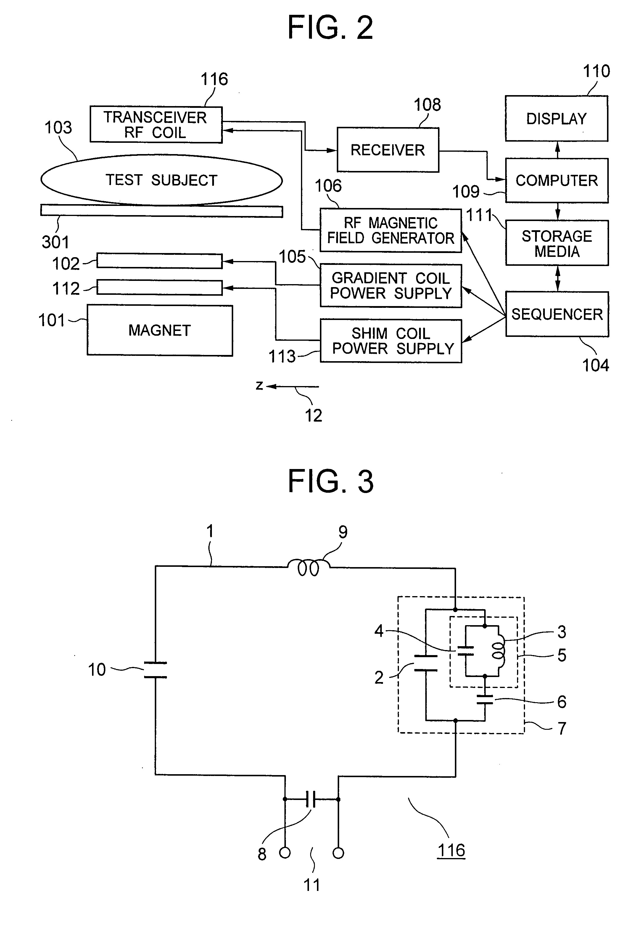
[0044]Next, an MRI apparatus according to the present invention will be described. FIG. 2 is a block diagram illustrating a schematic configuration thereof. The same reference numerals are allocated to the likewise elements in FIGS. 1A and 1B. The illustrated MRI apparatus comprises a magnet 101 for generating static magnetic field, a gradient coil 102 for generating gradient magnetic field, a shim coil 112 for adjusting static magnetic field uniformity, a sequencer 104 and a transceiver RF coil 116 for generating an RF magnetic field and the like. The gradient coil 102 and the shim coil 112 are respectively connected to a gradient coil power supply 105 and a shim coil power supply 113. The transceiver RF coil 116 is connected to the RF magnetic field generator 106 and a receiver 108. The sequencer 104 transmits commands to the gradient coil power supply 105, the shim power supply 113 and the receiver 108 which are caused to generate the gradient magnetic field and the RF magnetic f...

second embodiment

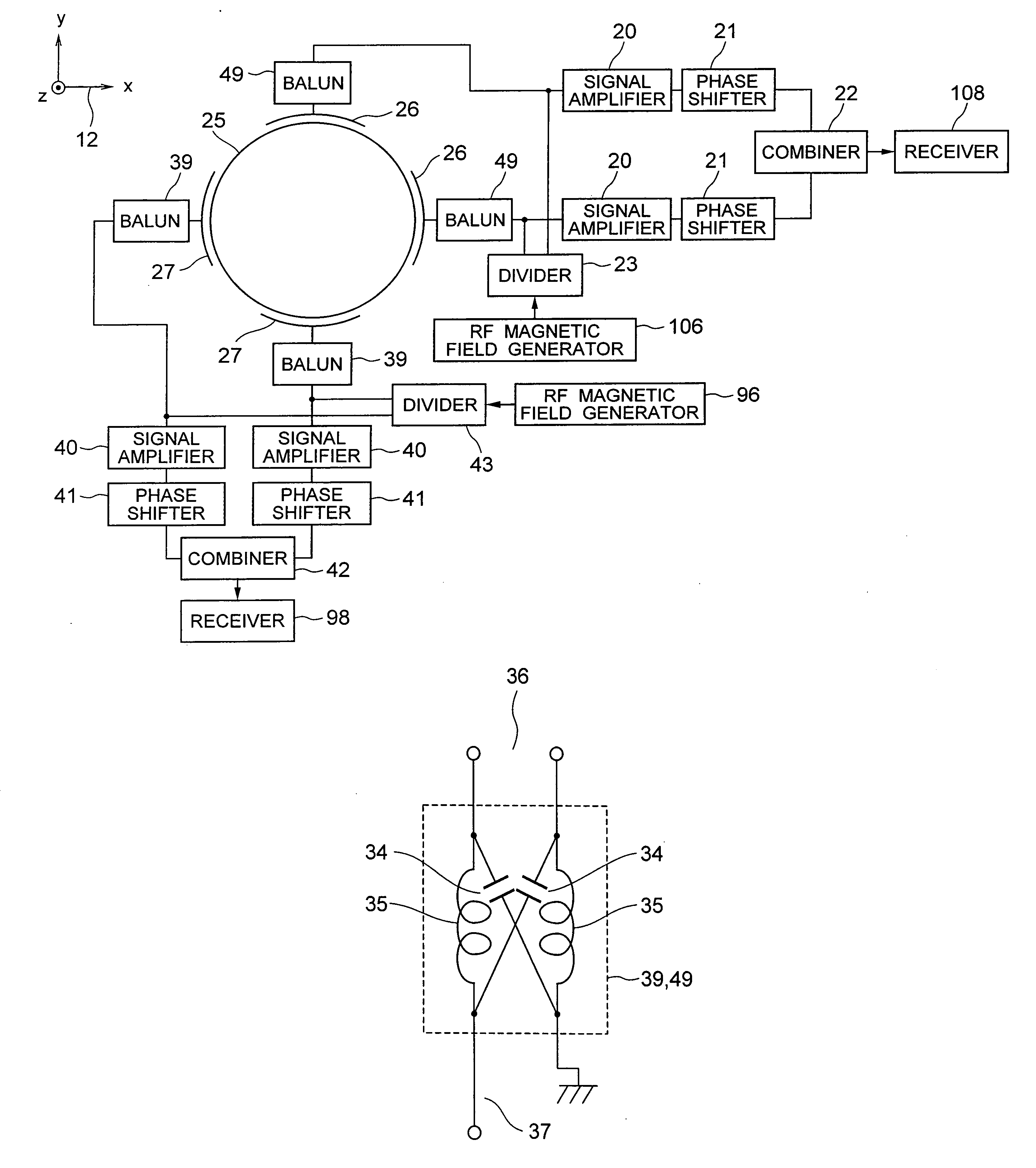
[0055]FIG. 5 illustrates a configuration of a double-tuned saddle type coil being the present invention. The coil of the present embodiment can be used as a transceiver RF coil 116 as well. The configuration in FIG. 5 is different from the embodiment in FIG. 3 in the point that the two opposite loops are connected to generate a magnetic field in the same direction in the loop conductor 1 and the respective loops have the planes presenting a shape subject to deformation so as to go along the virtual cylindrical side plane, that is a saddle type coil shape. The coil is shaped differently. However, the coil in FIG. 5 is the same as the loop coil in FIG. 3 in the circuit configuration and the operation principle. Accordingly, the coil illustrated in FIG. 5 operates as an RF coil for two magnetic resonance signals with mutually close two frequencies represented by combination of proton and fluorine nucleus. In addition, the saddle type coil has uniform sensitivity distribution in the reg...


PUM


Abstract

An RF coil has at least one conductor loop and a parallel circuit provided with a first branch and a second branch is installed. The first branch has a first capacitor and the second branch has a third capacitor and a first parallel resonance circuit configured by a second capacitor and a first inductor. The first capacitor has capacity to allow the RF coil to resonate at the time of transmission/reception of the first resonance frequency signal corresponding to an element with a higher magnetic resonance frequency, and capacity of the second capacitor and a value of the first inductor are determined as an accumulated value thereof based on the first resonance frequency. The third capacitor has capacity to allow the RF coil to resonate at the time of transmission/reception of the second resonance frequency signal corresponding to an element with a lower magnetic resonance frequency.

Description

INCORPORATION BY REFERENCE[0001]The present application claims priority from Japanese application JP2006-160818 filed on Jun. 9, 2006, the content of which is hereby incorporated by reference into this application.BACKGROUND OF THE INVENTION[0002]1. Field of the Invention[0003]The present invention relates to a magnetic resonance image pickup device (MRI: Magnetic Resonance Imaging) and, in particular, relates to an RF coil for detecting two types of magnetic resonance signal different in frequency.[0004]2. Description of the Related Art[0005]A magnetic resonance image pickup device is a medical imaging diagnostic device for making nuclei in any cross-section crossing a test subject cause magnetic resonance and obtaining a tomography image in that section from the generated magnetic resonance signals.[0006]The MRS (magnetic resonance spectroscopy) being a type of magnetic resonance image pickup method and the MRSI (magnetic resonance spectroscopic imaging) is used as a method for me...

Claims


Application Information

Patent Timeline
Patent Type & Authority Applications(United States)
IPC IPC(8): G01V3/00
CPCG01R33/34046G01R33/34069G01R33/34076G01R33/341G01R33/3685G01R33/3453G01R33/3635G01R33/3657G01R33/3678G01R33/345
Inventor SOUTOME, YOSHIHISAHABARA, HIDETAOCHI, HISAAKI
Owner HITACHI LTD
Why Eureka
Try Eureka