Fire retardant polymer nanocomposites for laser sintering

a technology of laser sintering and nano-composites, applied in the direction of additive manufacturing processes, applications, electric/magnetic/electromagnetic heating, etc., can solve the problems of reducing toughness, melting flow, releasing smoke and toxic emissions, etc., and achieve the effect of improving flame retardan

Inactive Publication Date: 2007-12-20
KOO JOSEPH H +2
View PDF11 Cites 35 Cited by
  • Summary
  • Abstract
  • Description
  • Claims
  • Application Information

AI Technical Summary

Benefits of technology

[0010] It is therefore an aspect of the present invention to provide a method and apparatus for producing free f

Problems solved by technology

Large amounts of metal oxides (>30%) are necessary to flame retard thermoplastics and in many cases compromises some mechanical properties of the thermoplastic such as reduced toughness, melt flow, etc.
Similarly use of halogens and/or phosphorous, nitrogen compounds also involves the addition of large amounts of additive(s) resulting in the release of smoke and toxic emissions when the modified thermoplastic is subjected to fire conditions.
It is important to note that the number of materials that perform effectively in selective laser sintering is limited.
Materials that resolidify or recrystallize quickly after melting tend to exhibit an in-build curl that results in unacceptable warpage.
Some materials, however, resolidify slowly

Method used


Image

  • Fire retardant polymer nanocomposites for laser sintering
  • Fire retardant polymer nanocomposites for laser sintering
  • Fire retardant polymer nanocomposites for laser sintering

Examples


Embodiment Construction

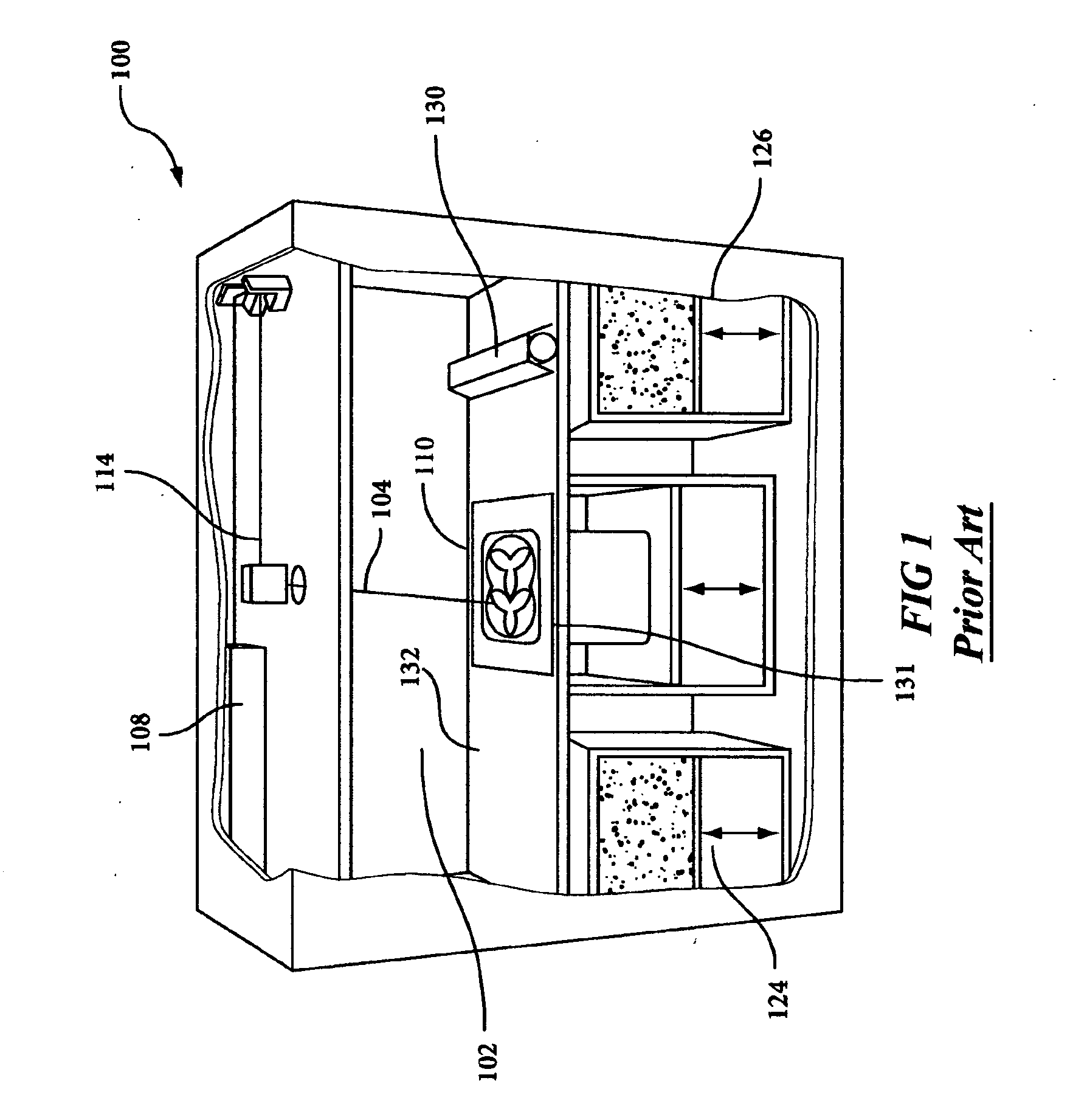
[0018]FIG. 1 illustrates, by way of background, a rendering of a conventional selective laser sintering system. FIG. 1 is a rendering shown without doors for clarity. A carbon dioxide laser 108 and its associated scanning system 114 is shown mounted in a unit above a process chamber 102 that includes a powder bed 132, two feed powder cartridges 124, 126, and a leveling roller 130. The process chamber maintains the appropriate temperature and atmospheric composition (typically an inert atmosphere such as nitrogen) for the fabrication of the article.

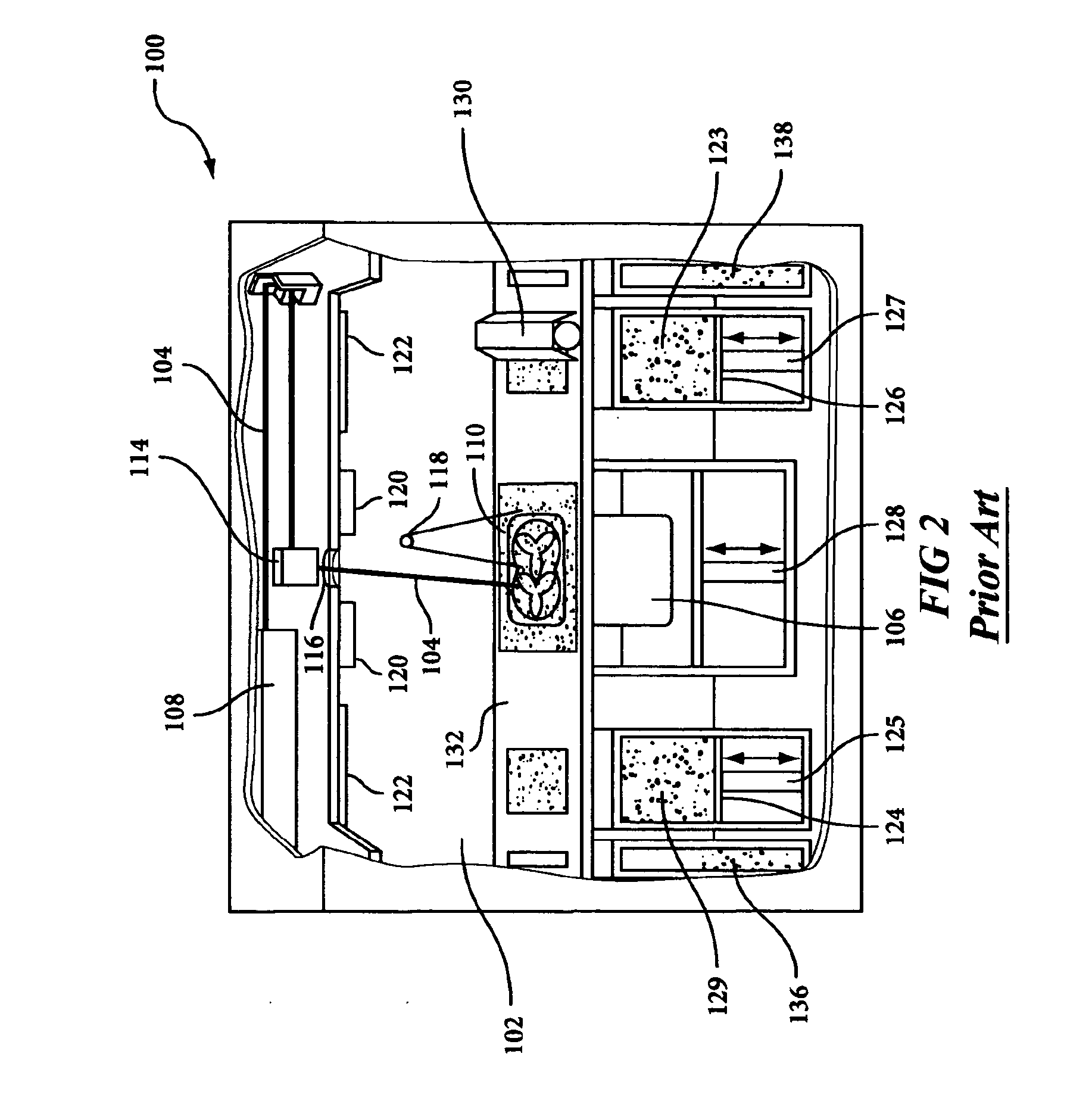
[0019] Operation of this conventional selective laser sintering system is shown in FIG. 2 in a front view of the process, shown generally as the numeral 100, with no doors shown for clarity. A laser beam 104 is generated by laser 108, and aimed at target area 110 by way of scanning system 114, generally including galvanometer-driven mirrors that deflect the laser beam. The laser and galvanometer systems are isolated from the hot chamber 1...


PUM

PropertyMeasurementUnit
Flame retardantaaaaaaaaaa
Spreading enthalpyaaaaaaaaaa

Abstract

A method and apparatus for forming three dimensional flame retardant objects by laser sintering that includes homogeneously combining, by an extrusion process, certain polymer materials with nanoparticles and using the resultant powder in a laser sintering device to produce freeform parts.

Description

BACKGROUND OF THE INVENTION [0001] This invention is in the field of solid freeform fabrication (SFF), and is more specifically directed to the fabrication of three-dimensional objects by selective laser sintering. [0002] Solid freeform fabrication (SFF) generally refers to the manufacture of articles directly from computer-aided-design (CAD) databases in an automated fashion, rather than by conventional machining of prototype articles according to engineering drawings. SFF has been embraced as a preferred tool for not only product development but in many cases, “just-in-time manufacturing.” The use of recently developed additive layered build fabrication methods of SFF, particularly selective laser sintering (SLS) have the potential to facilitate true flexible manufacturing of small batchs of parts “on-demand” while avoiding product-line tooling, under utilization of skilled labor and the need to maintain high overhead facilities costs. The field of solid freeform fabrication of pa...

Claims


Application Information

Patent Timeline
IPC IPC(8): B29C35/08B29C41/02
CPCB29K2105/16B29C67/0077B29C64/153
Inventor KOO, JOSEPH H.PILATO, LOUIS A.WISSLER, GERHARDT E.
Owner KOO JOSEPH H
Why Eureka
Try Eureka